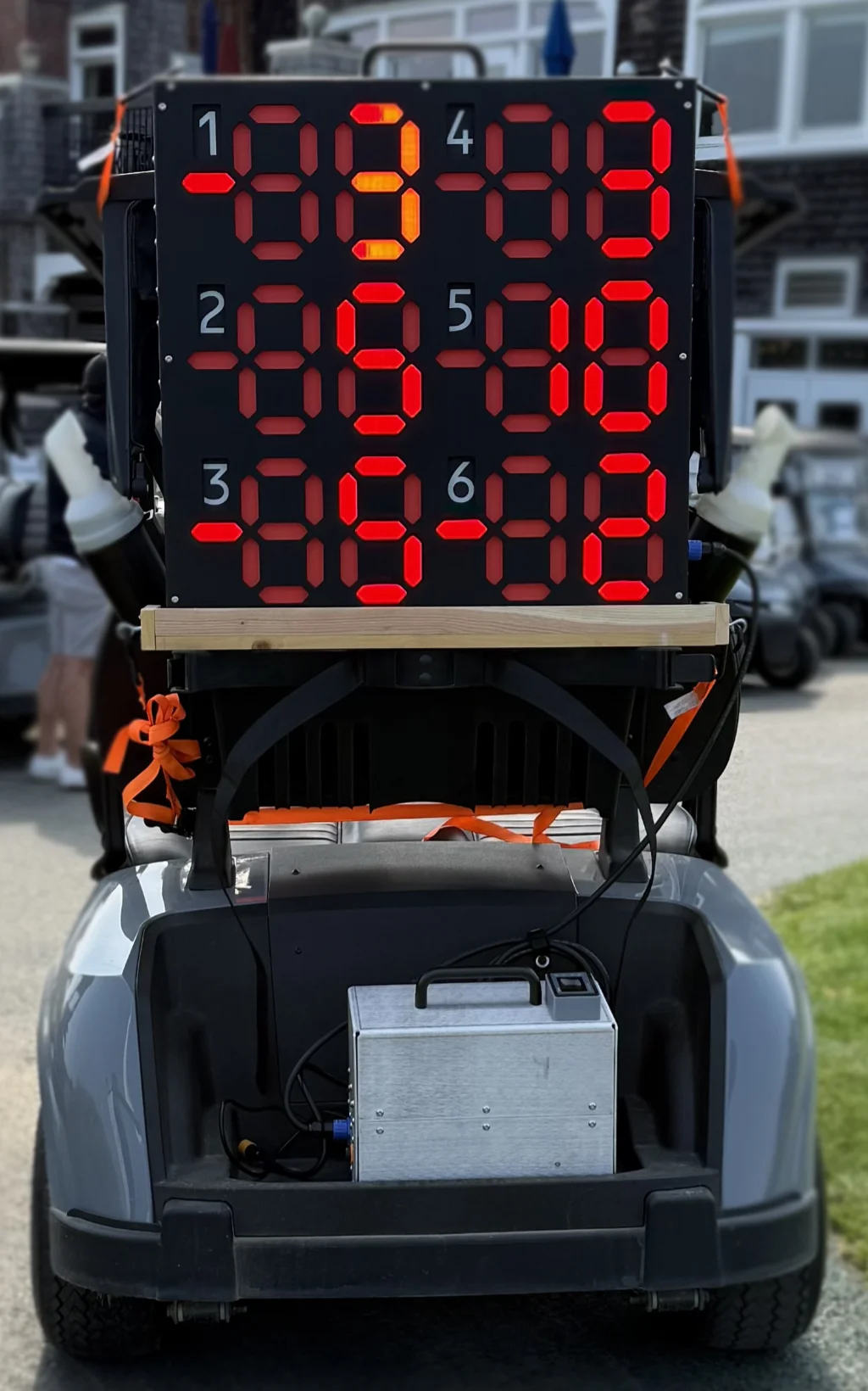
Custom Golf Scoreboard
This scoreboard was commissioned by a group that plays a special golf game once a year. I’m told it’s similar to H-O-R-S-E, but for golf. I started documenting the project with the intention of making a full video about it, but I ultimately needed to concentrate on finishing the scoreboard instead. Despite the date of this post, I’m actually publishing it in July 2026.
The basic idea was that the scoreboard needed to display the scores of six teams. Each team needed a two-digit score ranging from 00 to 99. Because scores could also go negative, the scoreboard needed a way to indicate that. Of course, there also had to be a method for adding to or subtracting from each team’s score.
There were four major challenges with this project:
- It had to be battery-powered and run for at least four hours.
- It had to be relatively portable, or at least capable of being strapped to the back of a golf cart.
- It had to be visible from a distance in daylight.
- It had to be durable.
If you know anything about electronics and batteries, you know that many of these requirements were in direct conflict with one another.
Oh, and did I mention they wanted two? One primary unit and one backup.
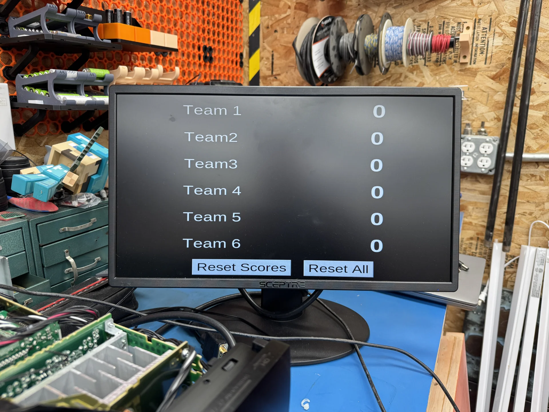
There was some back and forth over various ideas, along with a few tests. My first thought was to use an outdoor-rated display that could be seen in daylight and write a scoreboard application that would run on a Raspberry Pi. I could then connect a set of buttons to the Pi’s GPIO pins for score entry, or simply use a keyboard and mouse.
I coded a very basic proof of concept. It obviously would have needed a lot more polish, but it never progressed beyond this stage. Even though I found displays designed for outdoor use in direct sunlight that could also be battery-powered, it was ultimately decided that this approach wouldn’t work.
I then explored a seven-segment display design, initially testing NeoPixel strips in a 3D-printed housing. One of the original requirements was for the score to change color depending on whether it was positive, shown in green, or negative, shown in red. Unfortunately, the NeoPixels simply weren’t bright enough, even the higher-density versions, so I moved on from that idea.
They would actually make a very nice indoor display, but direct, and even indirect, sunlight is a difficult hurdle to overcome.
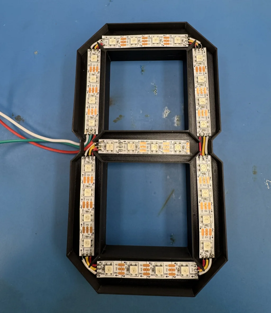
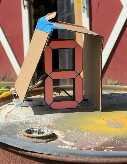
Even though the NeoPixels didn’t work out, they helped point me in the right direction. A traditional seven-segment scoreboard was clearly the way to go.
It was also decided that a single color, red, would be sufficient as long as there was a separate negative indicator. That simplified things quite a bit.
With only one color to worry about, the design became simpler, but I still had to determine what kind of LEDs to use. They obviously needed to be bright, but power consumption was also a major factor. After testing several options, I settled on some LED modules that I was able to pick up relatively cheaply on Amazon.
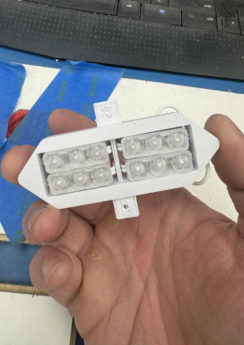
Each segment used four LED modules. This provided additional brightness while also ensuring that each segment was illuminated evenly. There were a total of 90 modules across the entire scoreboard. Power consumption added up quickly, reaching approximately 216 watts if every segment was illuminated at once.
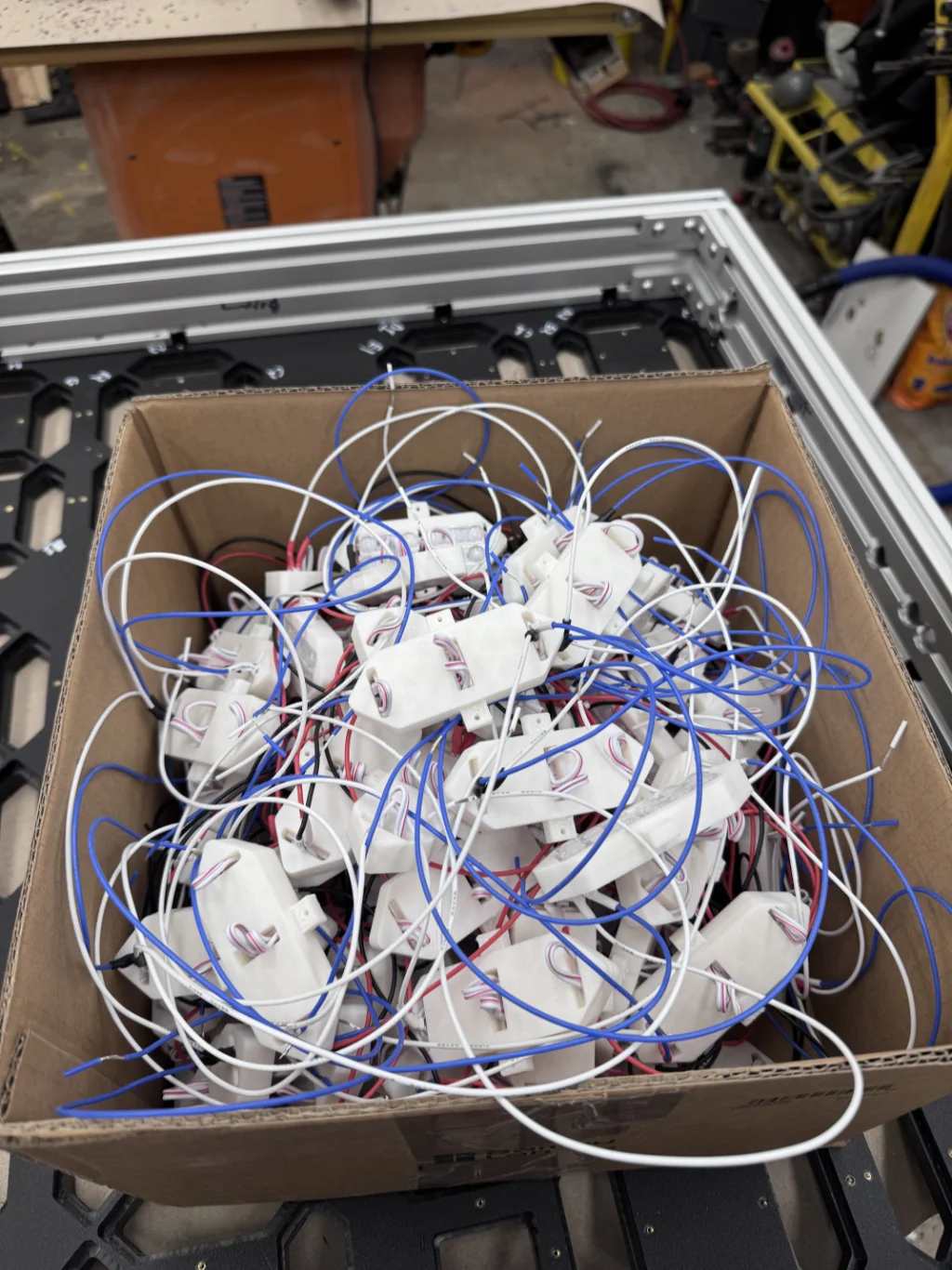
I designed and 3D-printed housings for the LED modules. The modules came with double-sided tape, which allowed them to be secured inside the housings. The completed housings would then fit into pockets machined into the scoreboard’s face.
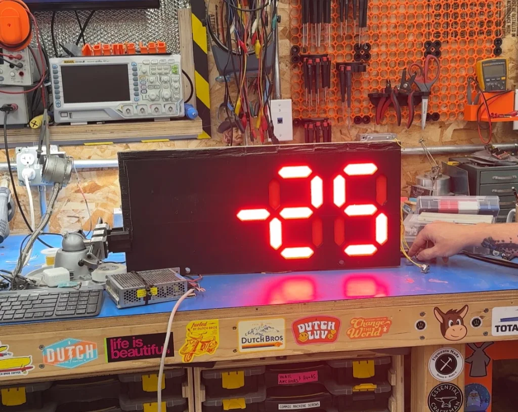
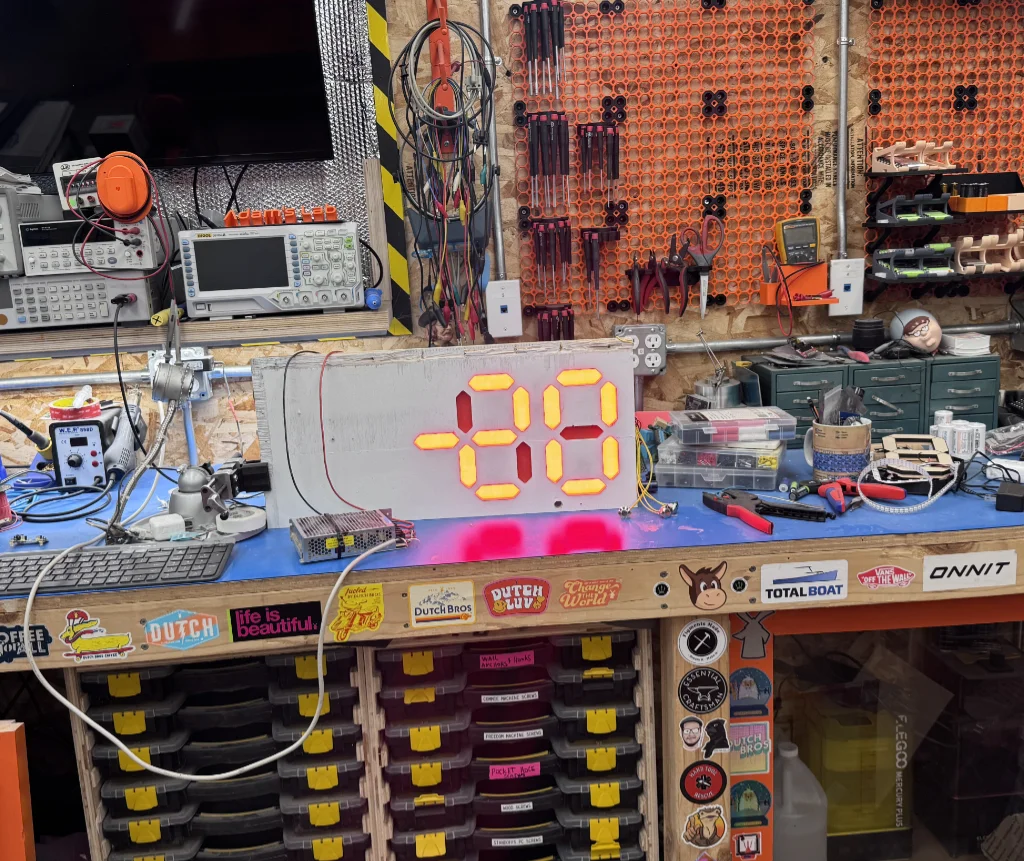
The original request was for the face of the scoreboard to be white. I recommended against this, but I needed to perform a test to demonstrate the difference and explain why a white-faced scoreboard would not work. The white surface would have completely washed out the LEDs, making an already difficult problem, seeing the LEDs in daylight, nearly impossible.
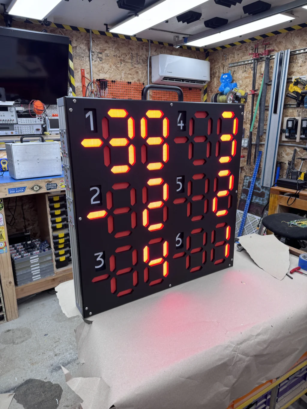
The face of the scoreboard was made from HDPE. I used my CNC router to machine pockets for the 3D-printed lenses and LED housings. It was important for the LEDs to be recessed because the shadows created by the recesses made them more visible in daylight.
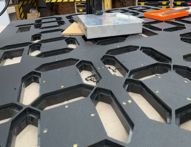
I used heat-set inserts to attach the LED housings and other components to the HDPE board.
HDPE is a great material. It is UV-resistant, impact-resistant, and waterproof. It is also easy to work with and can be cut using standard woodworking tools. However, it is expensive, so I was very nervous and careful while machining it.
Despite that, I still made one mistake.
An incorrect toolpath caused four of the recesses to be cut to the wrong size. Instead of cutting only the smaller LED openings, the CNC cut all the way out to the larger diameter of the rear recesses.
One of the properties of HDPE is that it is extremely resistant to chemicals. Unfortunately, that also means that most adhesives do not bond to it. I was worried that repairing the board would be difficult or impossible.
However, I found a 3M adhesive, DP8010, that is specifically designed to bond materials such as HDPE (note, you do need a special applicator to use it). I cut a tight-fitting ring for each incorrectly machined hole and bonded the rings into place. This recreated the correctly sized openings and recesses without requiring me to replace the entire board.
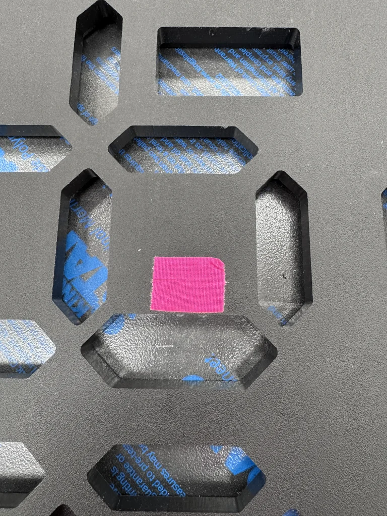
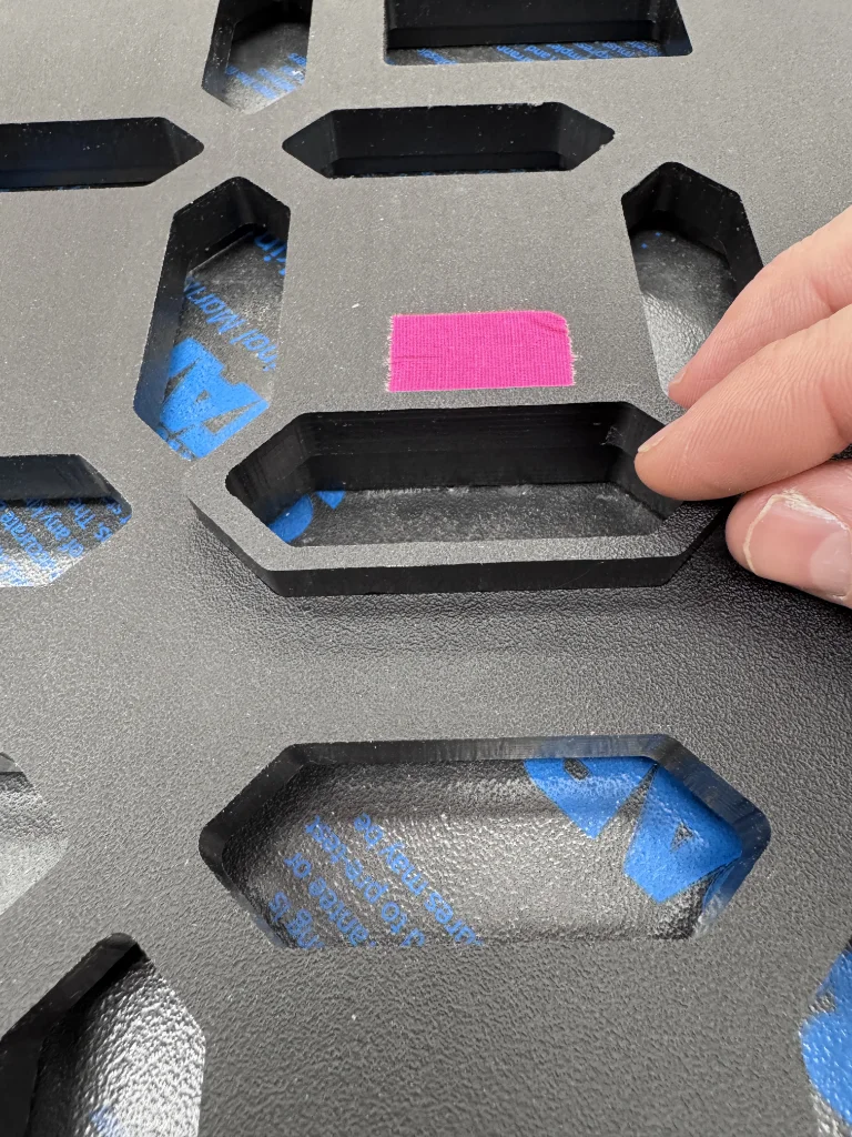
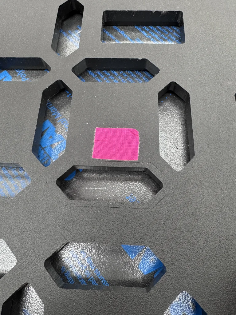
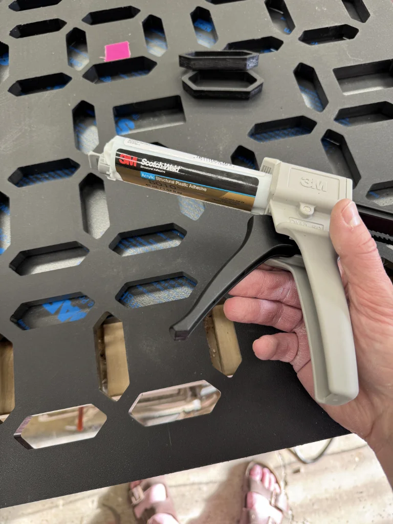
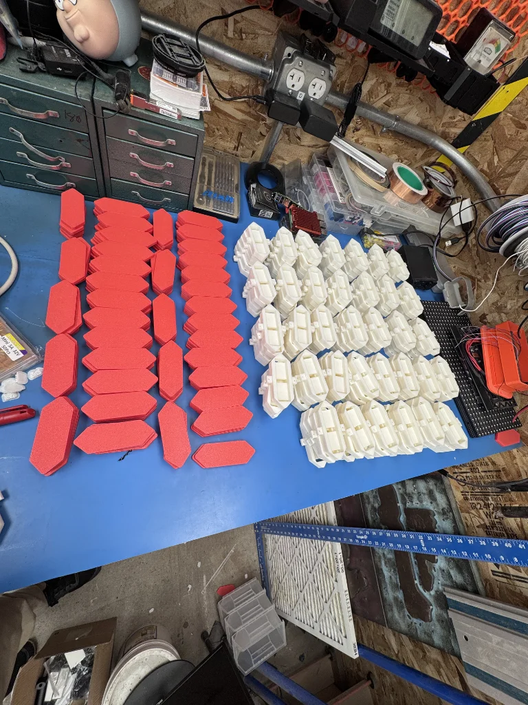
In total, I needed to print 180 lenses and 180 LED housings. I should mention that both the lenses and housings were 3D-printed using ASA, which I have found to be extremely robust in outdoor environments.
I considered several methods for controlling the segments. With 15 segments per team, plus the inputs needed to add to, subtract from, and reset the score, I needed a lot of I/O.
Ultimately, I decided to treat each team as its own independent system because that is essentially what it was. One team didn’t need to know what any of the other teams’ scores were, and I didn’t need features such as Wi-Fi or Bluetooth.
With that in mind, I decided to use a separate microcontroller, an Arduino Nano Every, for each team. There were certainly other options, most notably using a single microcontroller with shift registers or other I/O expander solution, but I ultimately decided that this approach made sense and kept things simpler. It allowed all of the inputs and outputs for each team to be controlled directly by its own microcontroller.
Each team’s score was stored in its Arduino’s EEPROM so that it would survive a loss of power. EEPROM has a limited write lifespan, but that was not a practical concern for this application. The score was written only when it actually changed, and the writes were distributed across six separate Arduinos. That was another small advantage of using a separate microcontroller for each team.
Each segment was controlled using a MOSFET. Since it would have been absolute murder to build six copies of the circuit on perfboard, I designed a custom PCB. In retrospect, adding a separate fuse to every LED segment was probably overkill.
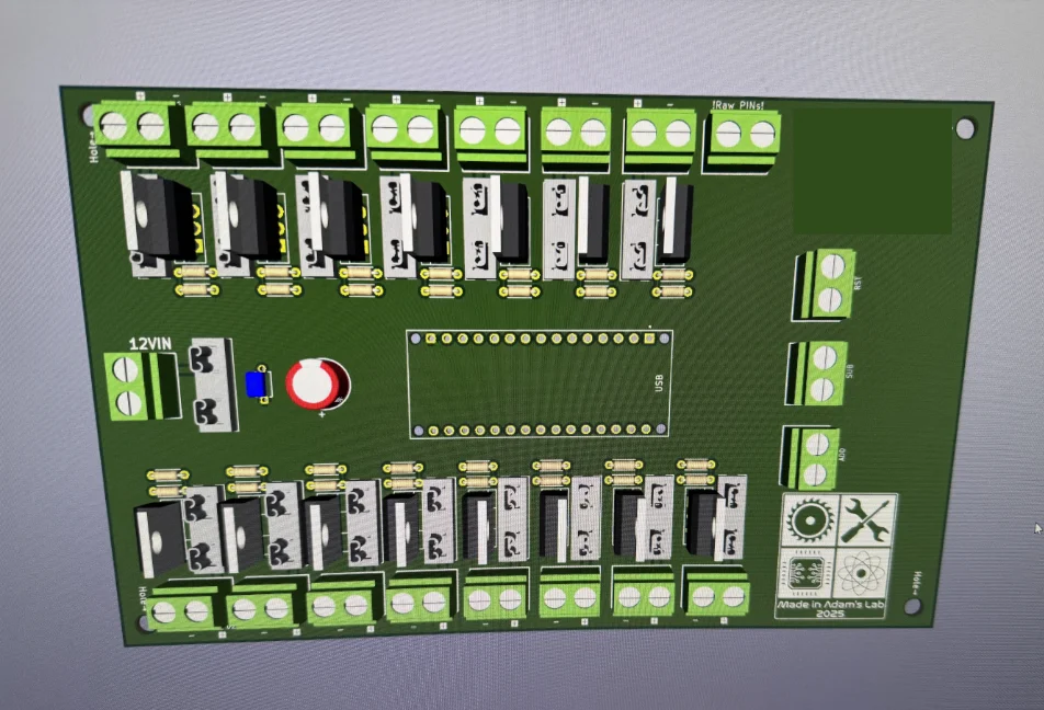
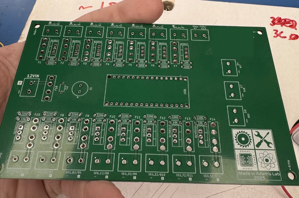
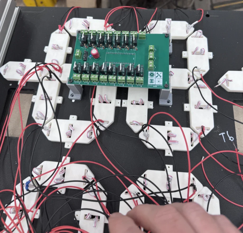
Wiring all of the segments was also kind of murder…
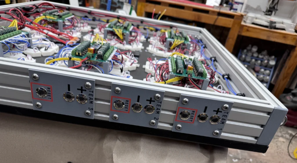
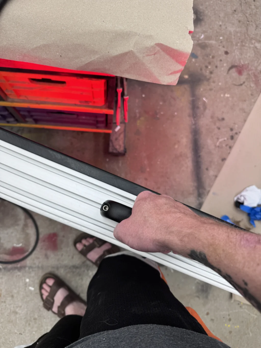
The scoreboard frames were made from T-slot aluminum extrusion. The only major downside was that the shape of the extrusion made drilling the holes and mounting the buttons somewhat difficult.
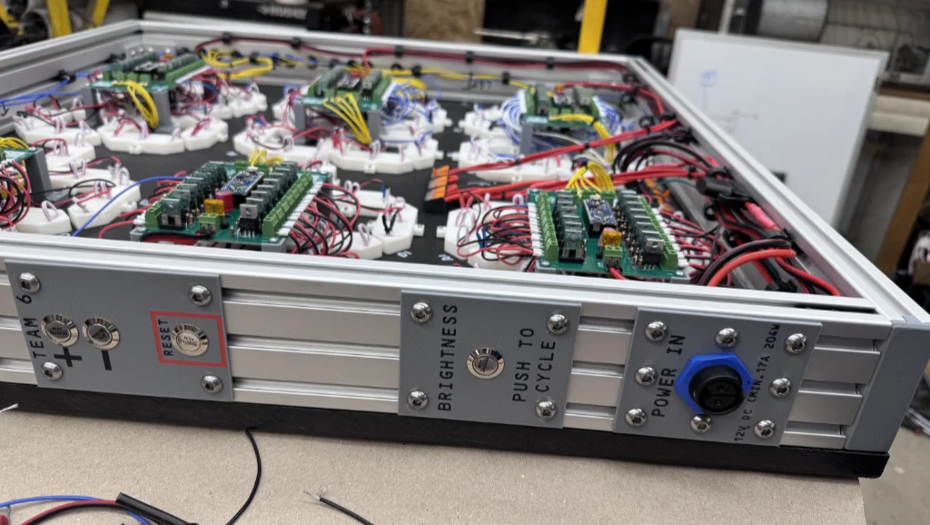
Each team had three buttons mounted along the side of the frame, with three teams on each side of the scoreboard. One side also had the power input and a button for controlling the display brightness. The panels that held the buttons and power connectors were all 3D-printed, again using ASA filament.
Brightness control was handled through software PWM. It was not strictly necessary, but I added it because running all of the segments at 50 percent brightness significantly reduced power consumption. Since the segments were energized only half of the time, on average, the scoreboard used considerably less power. The brightness could then be increased to full power if conditions required it.
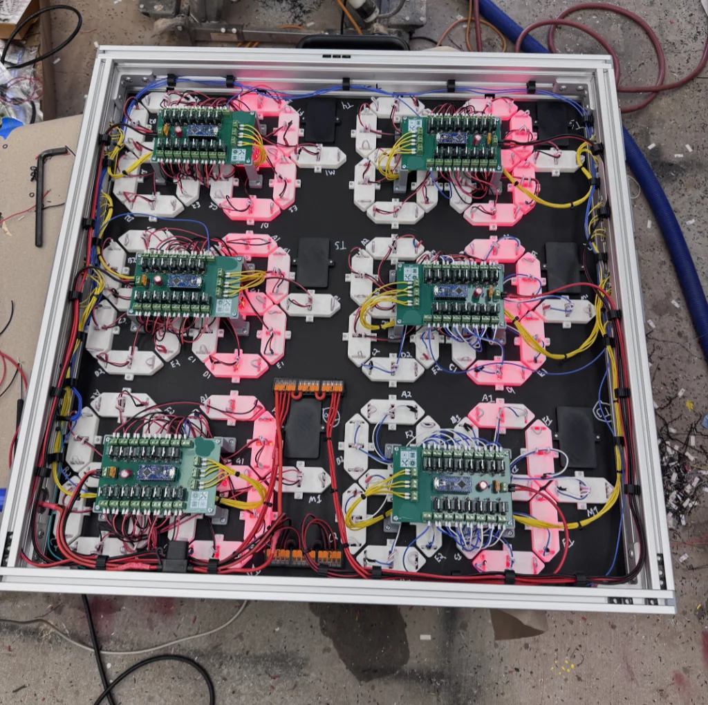
The teams didn’t have names, which was nice because it simplified things. They were simply identified as teams 1 through 6. I printed the number for each team and mounted it to the scoreboard using the same method as the LED housings.
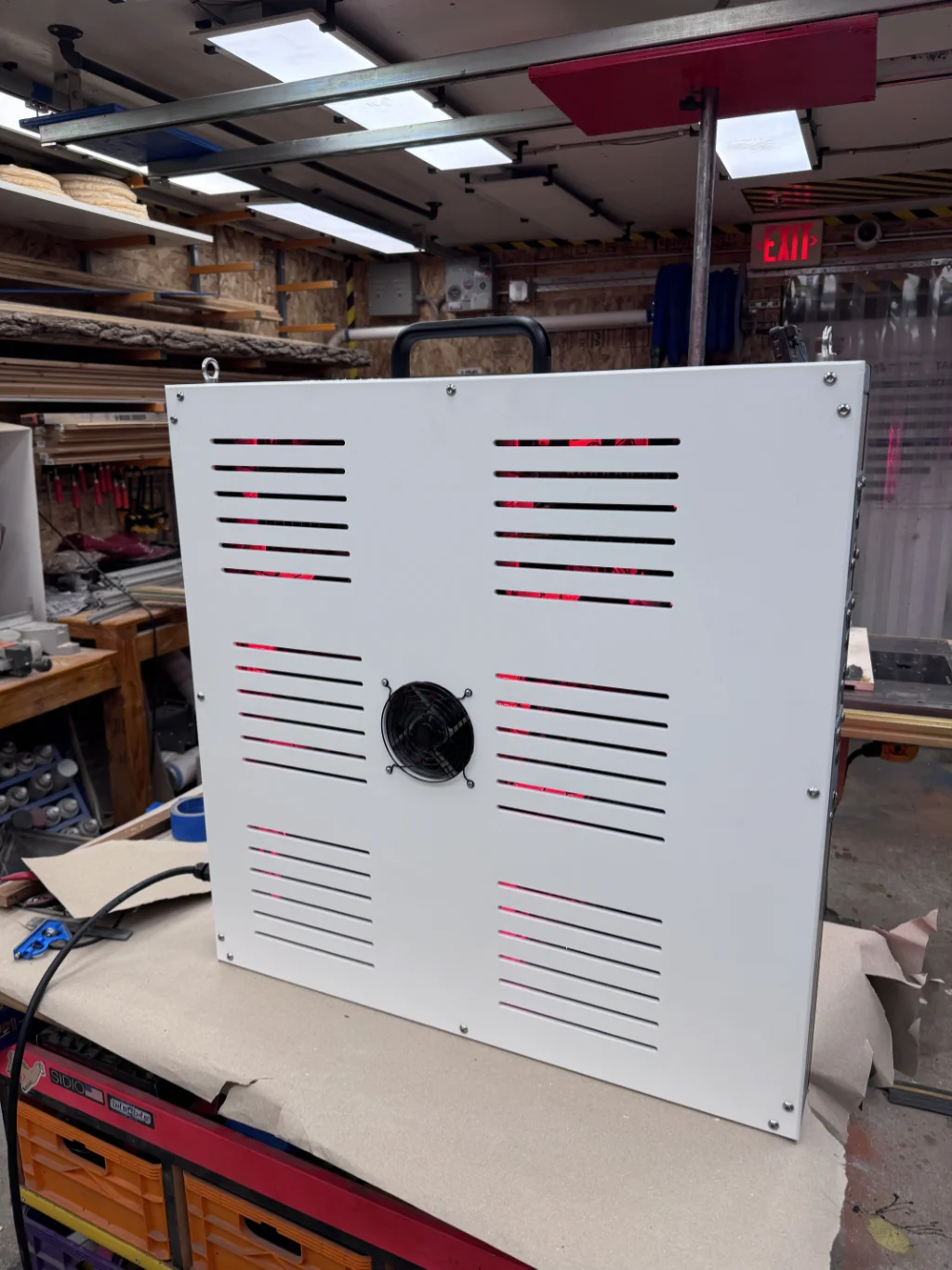
The back panel of the scoreboard was also made from HDPE, although it was thinner than the material used for the front. I machined ventilation slots into it with the CNC router and, although it was probably not strictly necessary, added a fan to provide airflow through the enclosure.
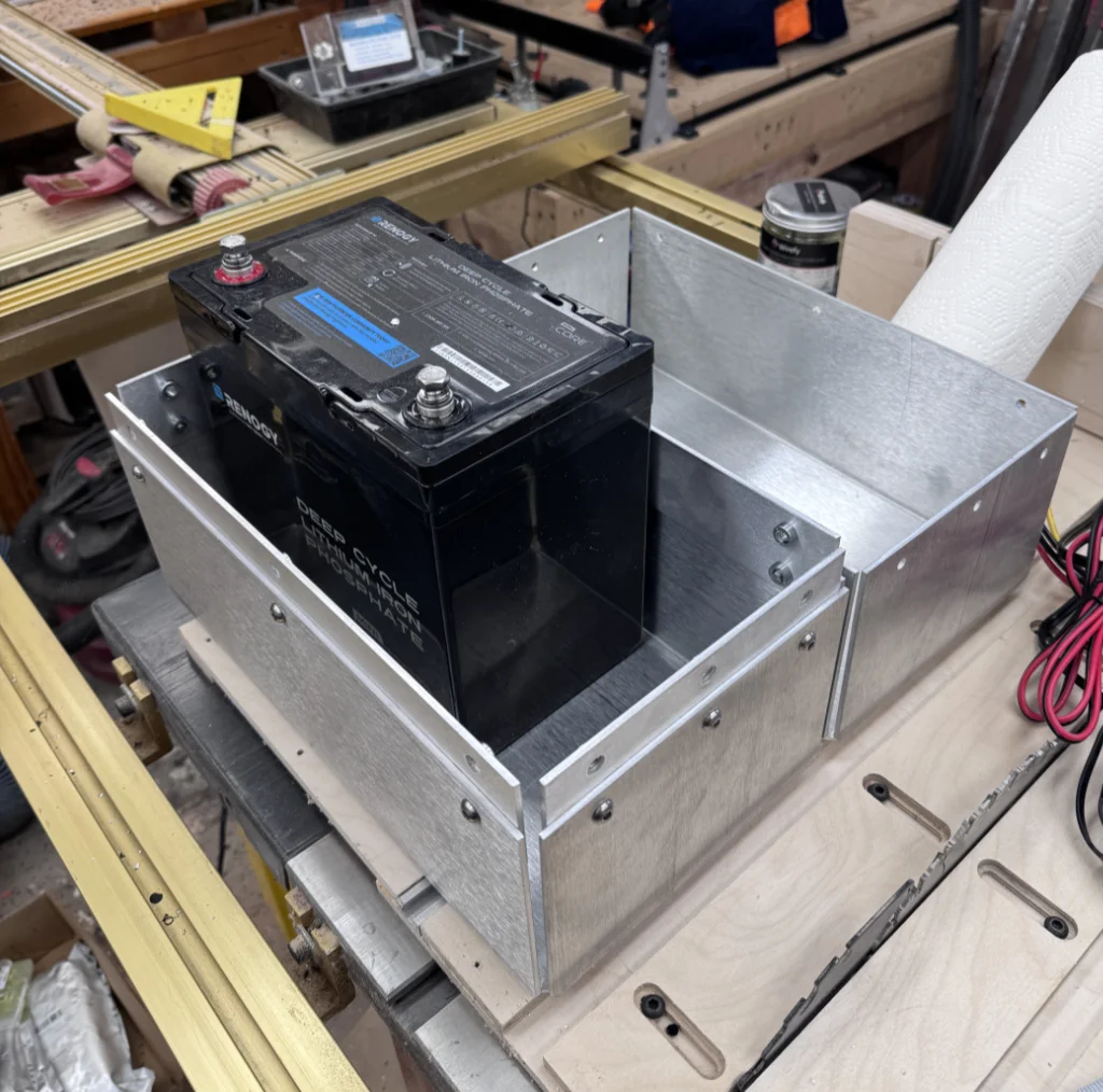
Finally, power was provided by a 100 Ah LiFePO4 battery. This was enough to power the scoreboard at full brightness for well over five hours.
Ideally, it would have been nice for the scoreboard to be completely self-contained, but with power consumption north of 200 watts, or roughly 17 amps at 12 volts, that was not practical. I designed a separate battery box and had the sheet-metal parts laser-cut and bent by SendCutSend.
The battery box housed the battery, a buck-boost converter to maintain a constant 12-volt output, a low-voltage cutoff, and a battery monitor that sounded an alarm when the battery reached a critical level. It also contained the necessary fusing.
This was actually my favorite part of the entire project. I love the way it turned out.
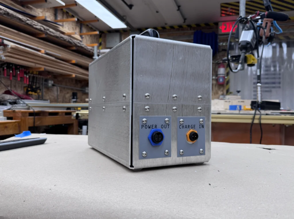
All told, the scoreboard weighed 46 pounds, and the battery box weighed another 34 pounds. It wasn’t light, but both pieces were manageable with their built-in handles. Besides, the scoreboard was going to be strapped to the back of a golf cart anyway.
The apparent differences in segment brightness in the photo below are caused by the interaction between the PWM frequency and the camera’s shutter. The brightness variation is not visible to the naked eye.