Lighted Address Numbers
A while ago the Wife Unit™ found some decorative metal numbers in a sale bin at the store. We both thought that they’d make great address numbers for the house and since they were dirt cheap we, bought them.
It didn’t take long for me to decided that I wanted to do something more than just hang them on the house. The numbers are raised, sort of reverse embossed, so the edges are exposed. My thought was to back-light the numbers for a cool nighttime effect.
Light Source
LEDs are the obvious choice for the light source, but since they are going to be outside they need to be weather-proof. I suppose, since they will be under an eave and “inside” the sign they won’t be directly exposed to the elements. Weatherproofing probably isn’t necessary but I think it’s a good idea.
I was originally thinking of sticking 5mm LEDs in some clear plastic tubing and sealing the ends with silicone. This would have worked fine, I think, but I found a better option. I came across some nice LED modules that are IP67 rated and cheep enough ($2.70) to justify using them instead of the tube/silicone method.
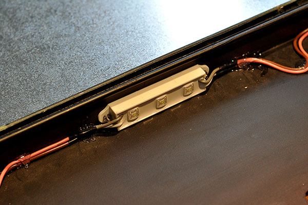
Dust and water tight LED modules. The three LEDs pull 25mA. Two modules were used per number.
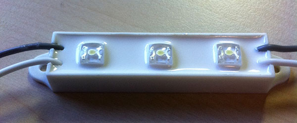
I decided that two LED modules per number, for a total of six modules, would be sufficient. The modules run off 12 volts and each module pulls 25mA; six modules would pull a modest 150mA. I used a regulated 12 volt power supply rated for up to 1.6A to insure the modules had plenty of power.
On/Off Without Thinking
Even though all the modules together only pull 1.8 watts, I still don’t want them on 24/7. There’s no reason they need to run during the day when you wouldn’t be able to tell they were on. Automation is a must, since there is no way we’d remember to turn them on or off.
There are lots of ways to do this I suppose, using and off the shelf timer would work, but timers are unreliable and need to be re-calibrated for seasons and daylight savings. A circuit that can detect when it was light or dark out and turn the LEDs on or off accordingly would be ideal. You can probably buy off the shelf devices that do this but off the shelf is no fun.
Before I started on this project I had come across some lovely light detecting circuit designs by Rob Paisley. I didn’t need them at the time but they seemed useful so I bookmarked his site for a time of need.
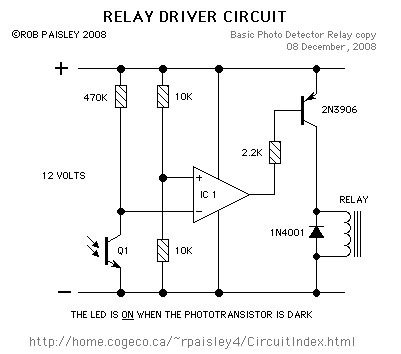 Photo Detector Circuit. Schematic by Rob Paisley, used with permission.
The circuit uses a phototransistor in conjunction with an LM339N quad comparator. The phototransistor is light sensitive, when the sensor is dark less current flows through it. The LM339N is used to compare a reference input voltage with the input voltage to the phototransistor and, as configured in the schematic above, trigger the PNP transistor which in turn triggers the relay. The PNP transistor and relay are used to allow more current to be controlled by the circuit.
Light Activated Switch from Adam on Vimeo.
Light Activated Switch (2) from Adam on Vimeo.
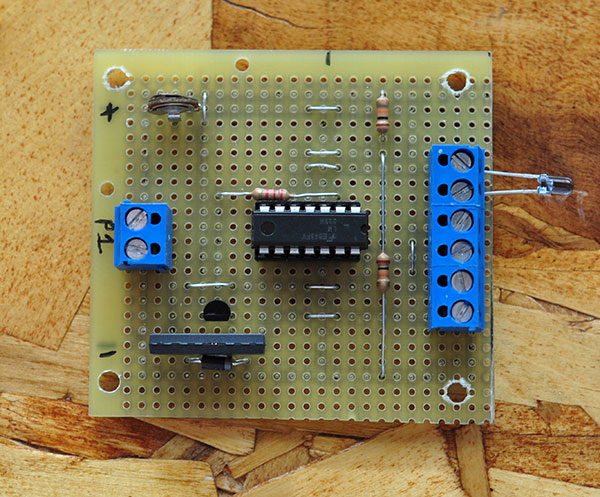 The finished photo detector circuit.
I mounted the photo detector circuit and power supply on a scrap piece of plexiglass. I was originally going to put the electronics outside, so I put them in a weatherproof enclosure.
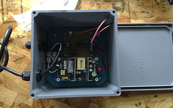 I had originally anticipated the electronics being outside, so they were mounted in a weatherproof enclosure.
Placement & Mounting
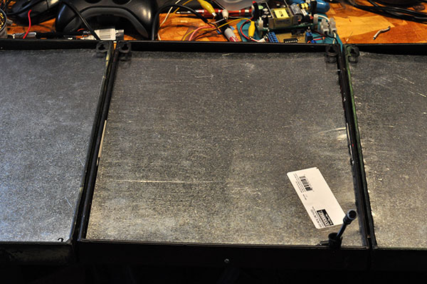
After some initial testing I found that the LEDs cast too much light from the back of the numbers. Since I didn’t want to light up the wall the numbers were hanging from, I added some galvanized metal to the back.
At this point I had also attached the numbers together so they were one unit. I used a small nut to maintain a small gap between the numbers. Attaching them together this way made running the wires between the individual LED modules and mounting easier.
We had initially talked about mounting the numbers near where the original (unlighted) numbers were. Based on this I anticipated the control electronics being mounted outside, likely under the eave of the porch where there was (conveniently) a 120v outlet. I also had to resign myself to the fact that there would be a visible wire going to the numbers. I figured that I could make it less inconspicuous by painting the wire the same color as the house.
However, after I had the numbers attached to each other so they were one unit, we found that their overall size was to big for the original spot, they fit but didn’t look right. After some thought we found a new place that actually ended up better for a couple of reasons.
-
The numbers would be more visible from the new spot.
-
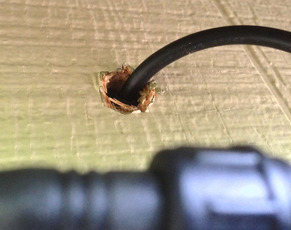
I would be able to have the electronics inside and run the wire through the wall to the back of the numbers; the wire would be completely hidden.
I was able to run a 2 pair wire from the spot the numbers would hang, through the wall of the house, through a coat closet, a bedroom closet and finally into a hall closet. Conveniently, there was already 120v running into the hall closet for the doorbell. I added an outlet so that I could plug in in the control box.
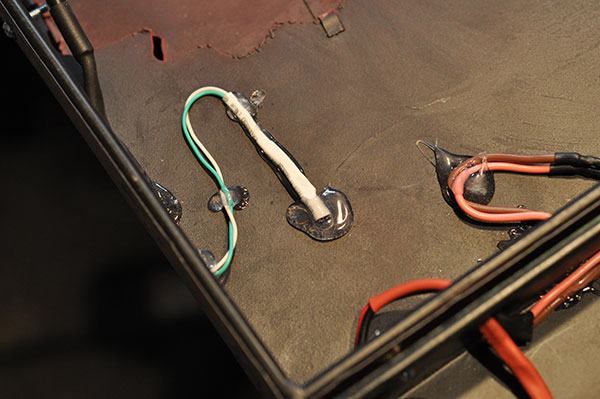
With the mounting figured out I decided that I would mount the phototransistor to the numbers. I drilled a hole in corner of the number 3 and hot-glued it in place from the back.
 Phototransistor mounted to the numbers.
 Control box mounted in the closet and plugged in
It sounds like a lot but the distance from the numbers to the box is only about 10′. By the time you account for how the wire was routed, the total length of wire used to connect the numbers to the control box was probably ~12-13′. I used a 2-pair 22 AWG low voltage cable – one pair was used for power and the other for the phototransistor.
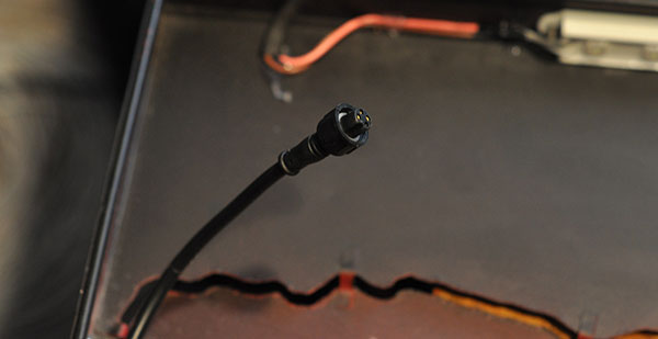
I used a waterproof 4-pin cable to come out of the wall and connect the numbers to the control box.
Ironic Problem
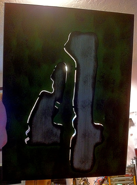
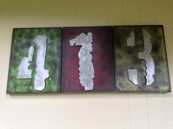
Once in place, we found that the numbers were difficult to see during the day. We realized that it was due to the contrast (or lack of) between the numbers and their respective backgrounds. After some thought I decided to strip the paint off the number part so the underlying metal showed. This gave us silver numbers against the respective backgrounds. I coated the now exposed metal with a clear coat to prevent rust.
Final Thoughts
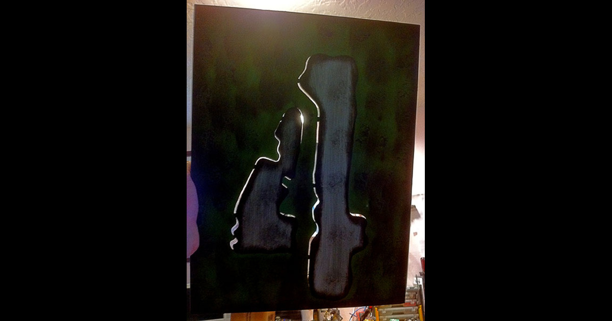
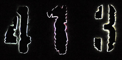
Overall we’re quite happy with the result. During the day the numbers are nice and big and (after we made them silver) are easy to see from the road. At night the LEDs light up the edges of the numbers to perfectly reveal their shape. The LEDs are just bright enough to do the job without being obnoxious.
I found it difficult to get a picture that exactly showed how they look but the one below is pretty close.
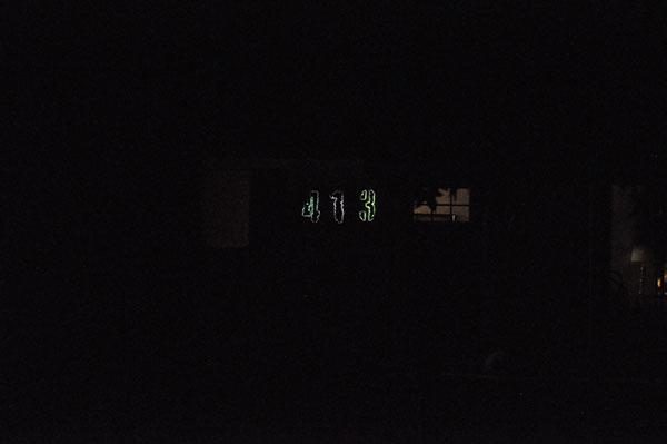 This is pretty close to how the numbers look. Note that I had turned our porch light off but even with it on the numbers are visible.
Notes
-
The 470k resistor shown in the Photo Detector schematic controls how sensitive the circuit is to light changes. I had originally used a trim-pot in place of the standard resistor. The trim-pot ended up breaking (it was salvaged) so I added screw terminal in it’s place so I could swap out a standard resistor easily. Obviously, once you get this dialed in, you should not have to change it.
-
As noted, the cable length between the control box and the numbers is ~12-13′. At that distance voltage drop was a concern, especially since I didn’t account for it. As it turns out, when you do the calculation for 22 AWG wire, the voltage drop is negligible but definitely something to keep in mind.
-
I have no idea who makes the numbers. There are no brand or manufacture markings. The UPCs were removed long ago. We found them ~3 years ago in the sale bin at Fred Meyer. They are probably not made anymore.