Mailbox Notifier

Note: since the original posting, I’ve added some updates (bottom of page).
Also see an updated version of this that uses an ESP8266 to send email notifications over WiFi.
A couple of years ago I came across some vintage light bulbs while perusing the aisles of Home Depot. Since then, I’ve been looking for a project to use them in. I thought that it would be cool to use one as an indicator light and started to form this picture in my head of what it would look like. I wasn’t sure what the bulb would be indicating, but the idea was now in my head and once I figured out what to use it for, I’d have to make it.
All that to say that this project was motivated by the need to make an indicator light using one of those vintage bulbs.
Somewhat Unimportant Backstory
Back in 2012 I posted a video demonstrating a vulnerability on a mailbox that was being marketed as a secure. After posting the video, the CEO of Architectural Mailboxes contacted me and explained that the mailbox shown in the video was an early design, which is no longer sold. The store where I shot the video was improperly using the old model for its display.
You can read the post for more detail but the CEO sent me an updated unit to test. Which I found to be lacking the vulnerability I had demonstrated.
All that to say, the mailbox used in this project is that mailbox.
The Problem
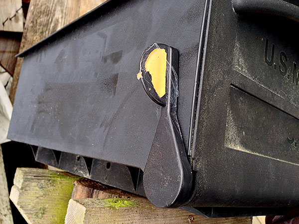
Our old mailbox has a plastic flag that is supposed to pop up when the mail is delivered. It’s woefully unreliable though, it either never worked or is just worn out. It’s also not user friendly because you have remember to put it back down when you retrieve the mail. If I got the mail but forgot to put the flag down, the Wife-Unit® would drive up thinking there was mail, only to find none. I’ve had an inkling to figure out a better way to show when the mail was delivered but was waiting till we got a new mailbox.
I’ve seen other projects that used various methods to show when the mail was delivered, some that texted, some tweeted but I don’t feel like I needed my mailbox to text or tweet. Since our mailbox is situated so that we drive past it on our way up the road to our house all that is really needed is a delivery indicator on the mailbox itself.
After Architectural Mailboxes sent me the updated mailbox and we decided to use it, I started to think about the problem a bit more and realized that I finally had a reason to make my vintage light bulb indicator.
The Idea
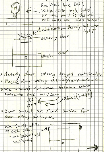
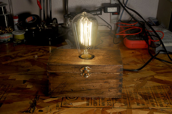
I’ll use LEDs on the mailbox to indicate when the mail has been delivered, and one of the vintage bulbs for a delivery indicator in the house. Both the LEDs and the bulb will automatically turn on when the mail is delivered and off when it’s retrieved.
-
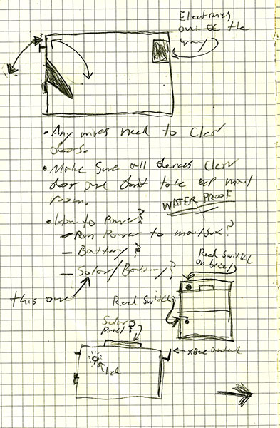
Power: The mailbox is +70′ away from our house with no power close enough to be of any use. While tempting, running power to the mailbox is not an option. The mailbox electronics will have to be battery powered. But batteries have their own shortcomings — i.e. I don’t want to have to change batteries in my mailbox. Solar power is an option but since the mailbox needs to run at night and in inclement weather I’ll have to use both solar and battery power. I’ll have to make sure that the mailbox electronics use very little power.
-
Trigger: How do I trigger the house indicator? I have the same distance and lack of wire issues as I do with power. The trigger will have to be wireless, which is ok because I have an inkling to use XBee radios for this.
-
Discreteness: I can’t alter the mailbox too much. I’m under strict orders to make any modifications as inconspicuous as possible.
-
Security: Since we are starting with a secure mailbox, it does not make sense to make modifications that would compromise that security.
-
Weather: The mailbox protects against gross water intrusion but it’s not completely moisture proof. Any electronics will have to be housed in an enclosure to protect against condensation. I’ll also have to be careful to maintain the mailbox’s existing water resistance.
-
Normal operation: I don’t want to piss-off the mail-person or the Wife-Unit®, so the notification system must not interfere with normal mail delivery and retrieval, it should not reduce the mailbox’s storage capacity, and it must be 100% automatic.
Primary Hardware
Arduino:
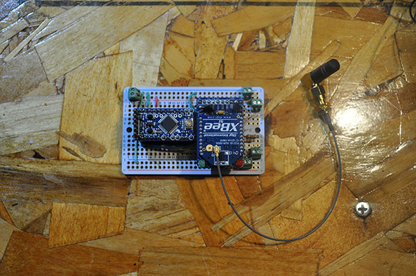
Specifically, the 5v Arduino Pro Mini. While I’ve found that I like the Boarduino for projects where I embed the microcontroller permanently, the Pro Mini is more than $7.00 cheaper and a lot smaller. The only practical limitation with the Pro Mini is its 150mA current limit. However, if you bypass the on-board voltage regulator and use a regulated 5v power source (connected to the VCC pin on the Pro Mini) you can ignore that limit. I’ll need two, one for the mailbox and one for the house indicator.
I’ll find later that using the 5v Pro Mini and basing the mailbox’s power system around that 5v requirement was a mistake.
XBEE:
I’ll use two XBee radios, one at the mailbox and one at the house so that I can wirelessly trigger the house indicator when mail is delivered and retrieved. The XBees run on a strict 3.3v for power and logic. Since I’m using a 5v Arduino I’ll use a adapter board with the XBees that will regulate the 5v power and logic. Regardless of any external factors, I’d still use the adapter boards since they breakout the non-standard XBee pins such that it makes them easier to work with.
It makes sense to house the mailbox electronics inside the mailbox, housed inside their own enclosure to protect against moisture. Since the mailbox is metal, and I’m already pushing the range limits of the XBee radios, I’ll use Series 1 XBees with the U.FL connector. The U.FL connector will allow me to connect an external antenna.
POWER:
No need to reinvent the wheel with for this. I’ll use Adafruit’s solar charger with a 6v/2w solar panel and a nice beefy 4400mAh Li-ion battery. Since the battery pack is 3.7v I’ll use a MintyBoost to bump the output voltage to 5v (it will also regulate it).
DOOR SWITCHES:
I’ll need some switches for the delivery and retrieval doors to connect to the Arduino so that it knows when the mail has been delivered or retrieved. I’m thinking I’ll go with reed switches for this but may try a button type switch.
LEDS:
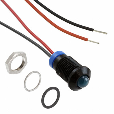
Seems trivial, but for the mailbox indicator lights I’ll need to figure out what kind of LEDs to use. If I mount them to the sides like I’m thinking, they will need to be able to stand up to the elements and be mounted in such a way that they don’t cause the mailbox to leak. They also need to be discrete and not stick out like a sore thumb. A DigiKey search turned up an LED that’s perfect. The only downside is their $10 price tag.
Mailbox Power
I did test beaming high-powered microwaves at the mailbox to charge the batteries. It worked well for charging the batteries but not so well for the neighbors cat.
he Adafruit solar charger does “Smart Load Sharing” which means that if the sun is out and the solar panel is producing power, the load output will be powered by the solar panel and not the battery (unless the device is pulling more current than the solar panel can supply). This is a neat feature, without it the charger would always have to power the load via the battery and charge the battery. It would also mean that at the same time you are charging the battery, you are discharging it. By pushing the load to the solar panel when it can, the charger can more efficiently charge the battery and reduce the charge/discharge burden on the battery.
However, the charger’s Smart Load Sharing does present a problem. The output voltage can go as high as 6v — the max voltage the solar panel can produce. This problem is solved though with the MintyBoost which, along with boosting the voltage, also regulates it to 5v.
I’ll find later that using the 5v Pro Mini and basing the mailbox’s power system around that 5v requirement was a mistake.
Getting Sleepy
Up to this point, other than making sure that I was operating within the limits of the hardware, I never gave the power consumption of an Arduino much thought. This is primarily because past projects have either been powered by mains or were short term battery powered. However, in this case I need the mailbox to run long term off battery/solar power. So, I have to be conscientious of the power that the devices are consuming.
If memory serves at idle (no sketch running on the Arduino and the XBee not transmitting or receiving) the Arduino and XBee draw ~30mA.
To calculate the estimated life of the battery I use the formula:
Battery Life = battery capacity in mAh / Load in mA * 0.7
(The 0.7 is used to factor for unknown external conditions that may affect battery life.)
Plug in the numbers:
Battery Life = 4400mAh / 30mA * 0.7
I get:
Battery life = 102.6 hours/4.2 days
4.2 days is quite a long time, except that it’s very likely there could be 4+ days without adequate sunlight to charge the battery. Remember also that this is a rough calculation and the safe bet is that the battery life would be less.
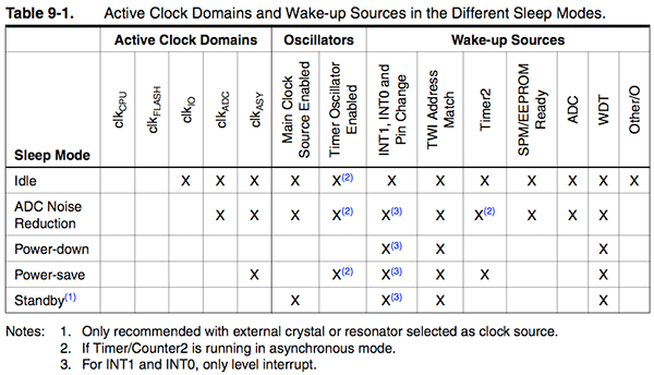
To reduce the power consumption I’ll have to use the sleep modes of the Arduino and XBee. When asleep the devices draw much less power with the tradeoff being that they are useless until woken up. When asleep, the Arduino does not run its sketch and will only respond to interrupts. The XBee can’t send or receive when it’s asleep and must be woken up by its internal clock or an external trigger.
There are various sleep modes for both devices, each with their own wake up method, use case, advantages and disadvantages. For both devices I’m going to use the sleep mode that offers the most power savings: SLEEP_MODE_PWR_DOWN (Arduino) and PIN HIBERNATE (XBee).
When asleep I found the Arduino and XBee draw: 11.9mA.
Battery Life = 4400mAh / 11.9mA *0.7
Battery Life = 258.8 hours/10.7 days
10.7 days is a more comfortable margin than 4 days. I’d expect that there would be enough sunlight in 10 days to keep the battery charged.
This assumption is later proved to be drastically wrong.
For the curious, the 5v Arduino Pro Mini by itself drew 0.81mA when asleep. That means the XBee accounted for roughly 11.09mA (asleep). Remember though that I’m using the adapter board which uses a regulator and a level shifter so some of that 11.09mA can probably be attributed to the inefficiency of that regulation.
The current consumption when the devices are awake and active (sketch running and XBee transmitting) is significant: 65.5mA — most of that is from the XBee. However, they will only be active and drawing that current for a short time.
The other power consumption factor is the delivery notification LEDs. I’m going to use two LEDs (one on each side) as delivery notifications. I want them to turn on and stay on until the mail is retrieved. Most of the time they will only be on for a few hours but there may be times when they are on all day, so it’s worth looking at their power consumption to avoid any surprises.
With the Arduino and XBee asleep and the notification LEDs on, the current draw is: 33.9mA. Subtract the 11.9mA the Arduino and XBee are drawing and I know the LEDs are drawing 22mA. This may seem odd for LEDs that are expected to draw 20mA each, except that I’m under powering them a bit to conserve power. They are still plenty bright.
At that draw (33.9mA) the estimated battery life would be 3.7 days. Since I expect that most of the time the notification LEDs will only be on for a few hours, with only the occasional day long stint, I think this is acceptable.
More On Sleeping
XBees have two sleep modes: cycle-sleep and pin-sleep. Cycle-sleep uses the XBee’s internal clock to wake and sleep the radio and specific intervals. Pin-sleep lets you put the XBee to sleep by pulling the DTR PIN HIGH. I’m using pin-sleep because it offers the most power savings and can be controlled by the Arduino.
To put the XBee to sleep you first have to set the sleep mode using the X-CTU software. Then connect the DTR PIN to a PIN on the Arduino and do a digitalWrite(XBeePin, HIGH); in the sketch when you want the XBee to sleep and digitalWrite(XBeePin, LOW); when you want it to wake up.
The Arduino, has several sleep modes and several ways to wake up too. I’m using SLEEP_MODE_PWR_DOWN because it uses the least power and (conveniently) can be woken up via an external interrupt (i.e. button press/switch).
In this case the interrupt will be triggered by switches when either the mailbox delivery or retrieval doors are opened. The Arduino will wake up, wake up the XBee, do the necessary processing, put the XBee to sleep, and then put itself to sleep.
The good thing about the Arduino’s sleep modes is the PINs stay in the state they are in when the Arduino goes to sleep. So, if a PIN is LOW it stays LOW and if it’s HIGH, it says HIGH. This works out because the XBee needs to see a HIGH signal to stay asleep and we also need to keep the delivery LEDs on (i.e. HIGH) when the Arduino is sleeping.
Triggering The House Indicator
In this setup the XBee’s are going to be used as a wireless serial link between the mailbox and the house Arduinos. The mailbox Arduino will be programmed to do a Serial.println(“1”); when mail is delivered and a Serial.println(“0”); when mail is retrieved. When the house Arduino receives a “1” it will turn the indicator light on and off when it receives a “0”.
Detecting Mail Delivery And Retrieval
Since the mailbox has separate doors for mail delivery and retrieval it makes it easier to setup a system to detect mail delivery and mail retrieval as distinct and separate events. I can safely assume that when the delivery door is opened that the mail has been delivered and that it has been retrieved when the retrieval door is opened.
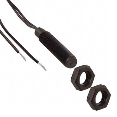
I’ll use two reed switches mounted to the mailbox with a magnet attached to the doors to detect when the doors are opened.
Reed switches come in all shapes, sizes and configurations. Another DigiKey search turned up what looks like perfect candidate. The way they mount is ideal and they are completely weather proof.
The two reed switches will be connected to the Arduino on separate PINs. They will trigger interrupts that will wake the Arduino when either one of the doors is opened. It may be a good idea to program the Arduino to ignore the retrieval door opening if the delivery door has not opened already. In that vein it should also ignore the delivery door opening if it’s already recorded that it’s been opened. This will prevent the system from running unnecessarily and prevent abuse.
The House Indicator
This section deals with Mains Power, which can kill you dead, cause severe injury, fire and/or other damage, and is generally just scary. I’m in no way responsible if you injure, kill yourself or others, cause damage to your property or other’s property, or otherwise use this information stupidly.
The house indicator presents a special problem because the light bulb I want to use operates on 120Vac. The max input voltage of the Arduino is 5Vdc. So we need a way to safety interface the high voltage light bulb with the low voltage Arduino.
Fortunately I’ve done this before and it’s actually quite easy. I could use a ready-made relay (either mechanical or solid state) but I have the parts to make a custom circuit.
The circuit uses an opto-isolated triac (MOC3020M) to trigger a second triac (2N6073) that has the high voltage load on it. The MOC3020M is not meant to carry the high voltage load, it’s only meant as a trigger device for another suitable triac.
This is basically how Solid State Relays (SSR) work. In fact the only difference between this circuit and an SSR is that it’s a bit cheaper to make this vs. buying an SSR. Buying the SSR is easier, so there’s that. If in doubt, buy an SSR.
In any case, this circuit allows the Arduino to switch a high voltage load while keeping it completely (electrically and physically) isolated from the high voltage side.
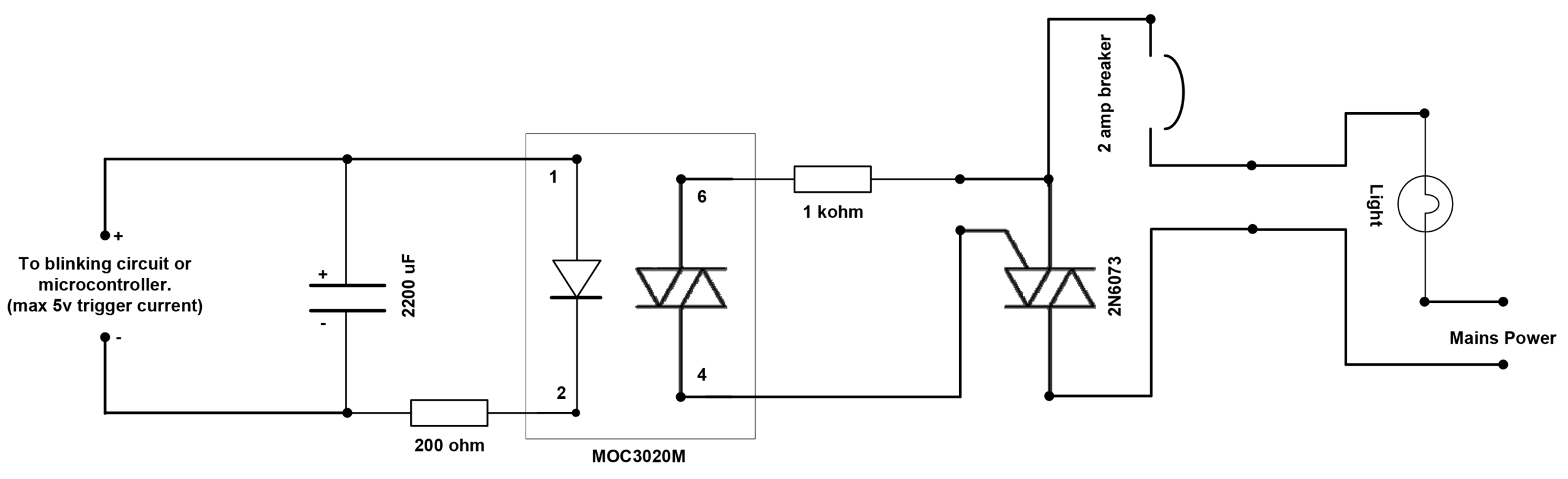
The vintage light bulb is 40 watts so it doesn’t even draw an Amp of current. The load carrying traic (2N6073) is rated to 4 Amps (if properly heat-sunk) so it’s more than adequate for this use.
The Build
This will mostly be pictures with some explanation where I think it’s necessary. Pay attention to the picture captions.
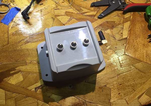
Reed Switches
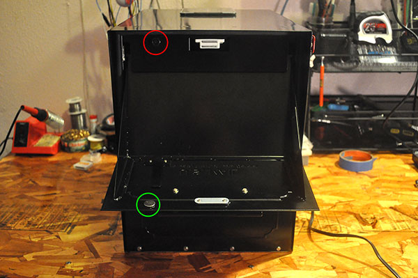
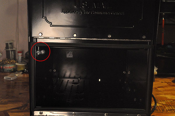
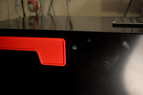
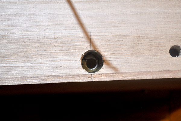
My first concern was figuring out how to mount the reed-switches. Turns out that it was pretty simple. For the delivery door I drilled through the front bezel and attached the reed-switch to the frame of the mailbox. For the retrieve door I used a corner bracket mounted to the mailbox with an existing bolt, a wire tie-down held the reed switch in place.
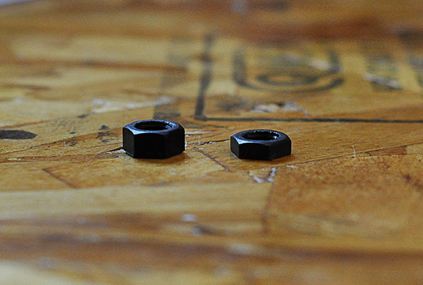
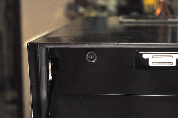
I did have to shave some material off the outside bolt for the delivery reed-switch so that the delivery door would close properly.

The original sized bolt on the left with the shaved bolt on the right.
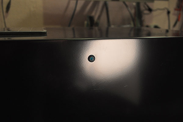
Red circle is the delivery reed switch. The green circle is the delivery door magnet.
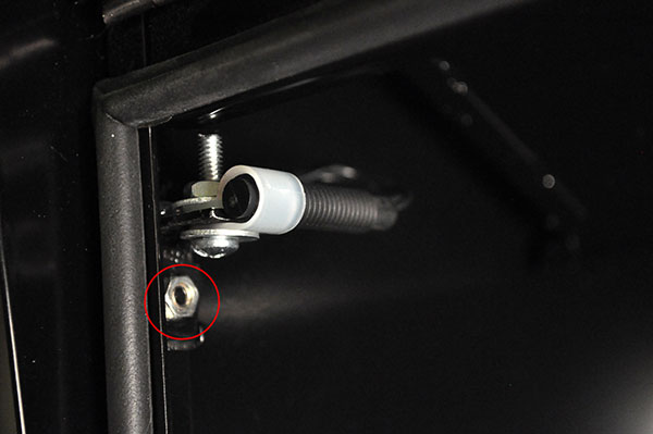
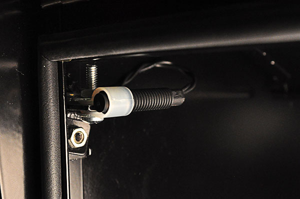
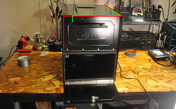
The retrieve door switch was mounted to the frame of the mailbox with a corner bracket and a wire clamp.
The red and green lines show roughly how the switch wires were run inside the mailbox. Hot-glue, sticky-backed tie downs, and hope were used to hold them in place
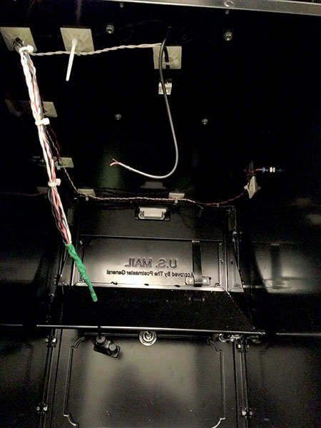
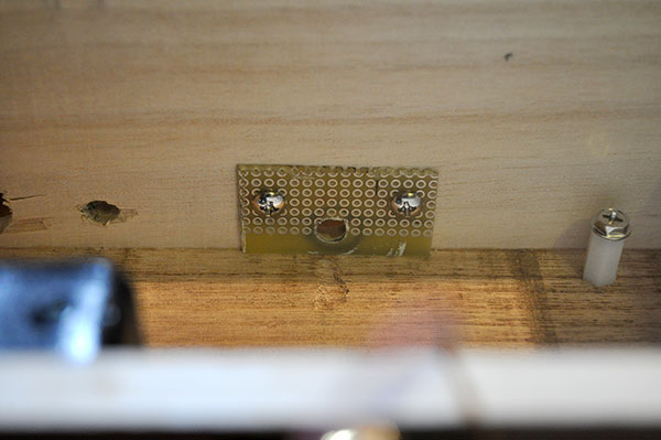
You can roughly see how the wires were run in this pic. The retrieve switch wire is hot-glued into the right corner. You can also see the right notification LED and the dome light (white square in the center) that was added for giggles.
Notification LEDs
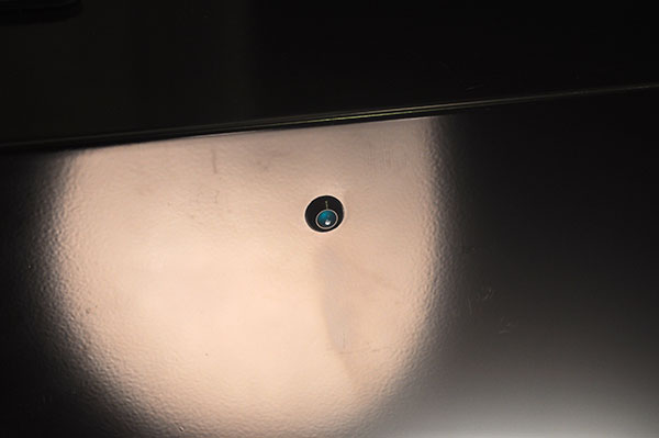
The two notification LEDs were mounted to the sides via holes I drilled in the sides of the mailbox. As noted the LEDs are IP67 rated and include an o-ring to seal the mounting hole.

I should probably note that the back of the mailbox is bolted on, so I was able to remove it to run wires and mount things.
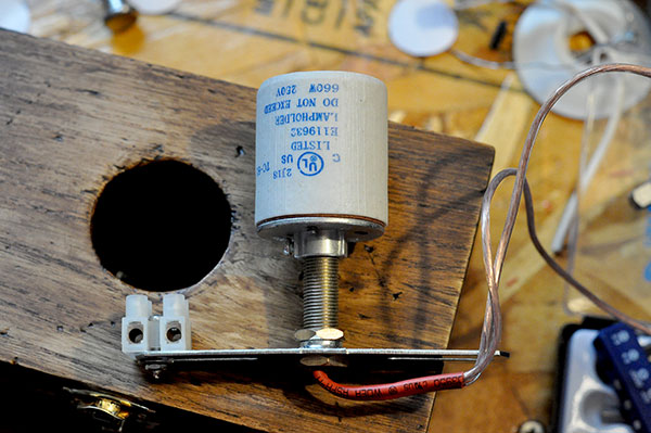
Solar Panel
I debated on where to place to solar panel. I wanted to to mount it on the back facing south at 45° (supposedly the ideal placement for our region) but the Wife-Unit® thought that it would be too noticeable, which is true, so I mounted it on the top of the mailbox.
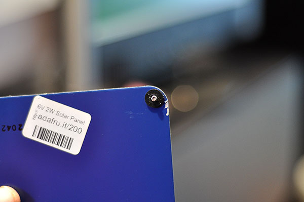
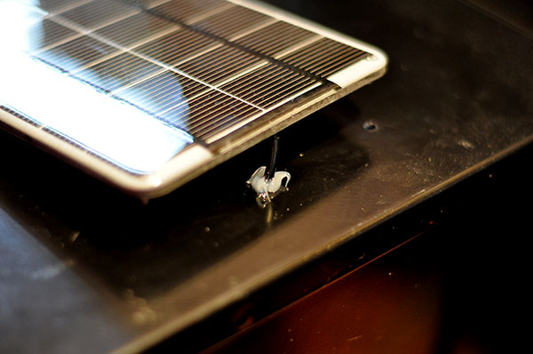
I drilled 5 holes: 4 for the mounting bolts and one for the panel wire. I used rubber washers to seal around the mounting bolts and a glob of clear silicone caulking around the wire entry point.
The Solar panel never leaked but I didn’t like how rain-water would collect and sit under the gap between the mailbox and solar panel so I ended up running a bead of caulking around the entire panel.
Rubber washer on the bolt to seal around the opening.
Plenty of silicone caulking… leaking would be bad.
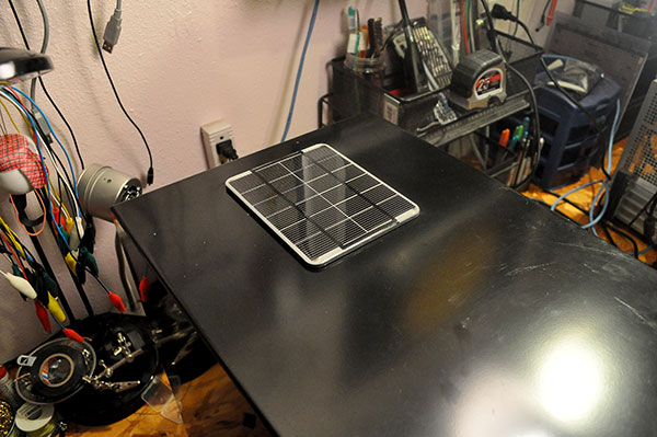
The solar panel is waterproof, scratch resistant, and (ironically) UV resistant.
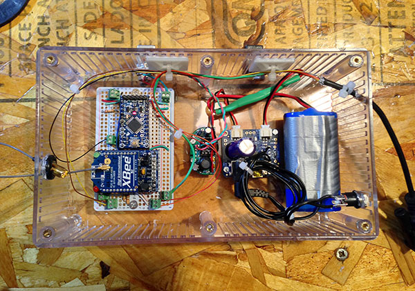
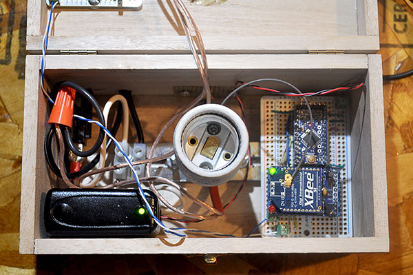
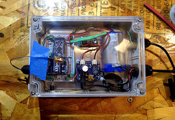
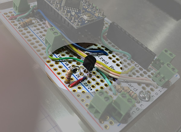
Mailbox Electronics
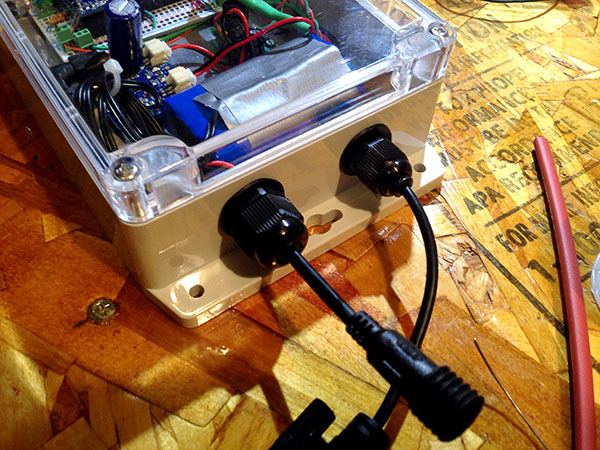
The Arduino and XBee were socketed to the protoboard so they are easily removable (this turned out to be very handy later). Screw terminals were used for all the wires that needed to connect to the board.
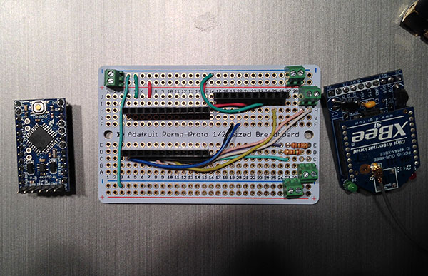
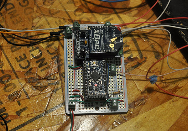
This was the first enclosure I tried. Not water/air tight but I just needed to protect everything from condensation. The Arduino and XBee are on the left. MintyBoost is on the middle-left and the solar charger is on the middle-right. The blue thing on the right is the battery, there is a temp sensor taped to is so the charger can decide if it’s too cold or hot to charge.
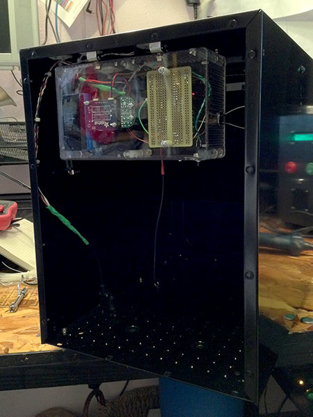
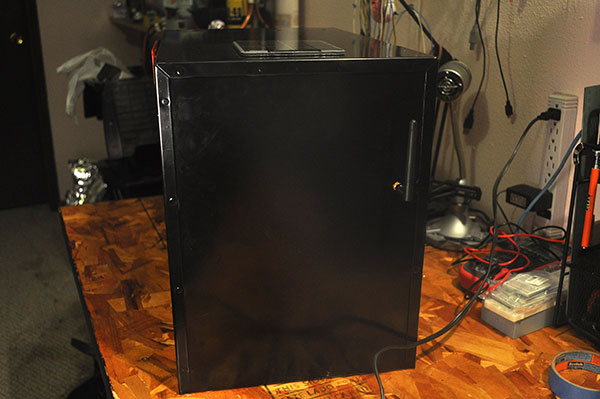
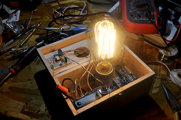
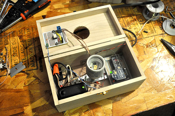
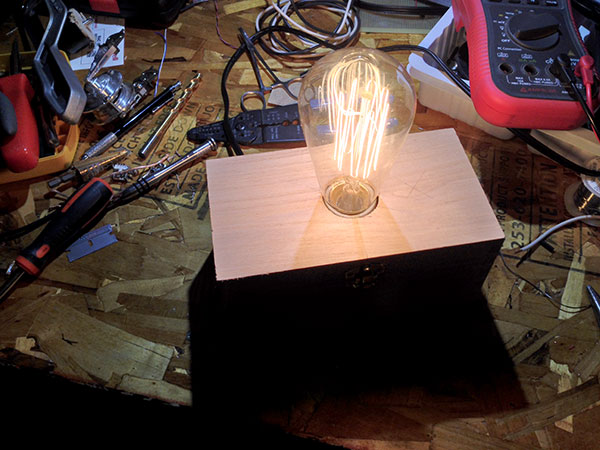
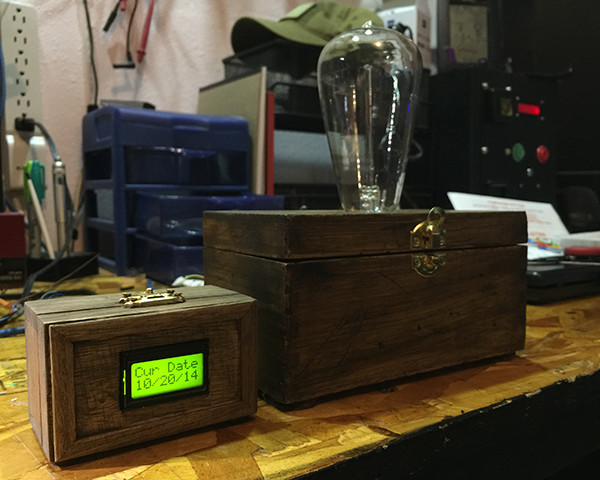
House Notification
This section deals with Mains Power, which can kill you dead, cause severe injury, fire and/or other damage, and is generally just scary. I’m in no way responsible if you injure, kill yourself or others, cause damage to your property or other’s property, or otherwise use this information stupidly.
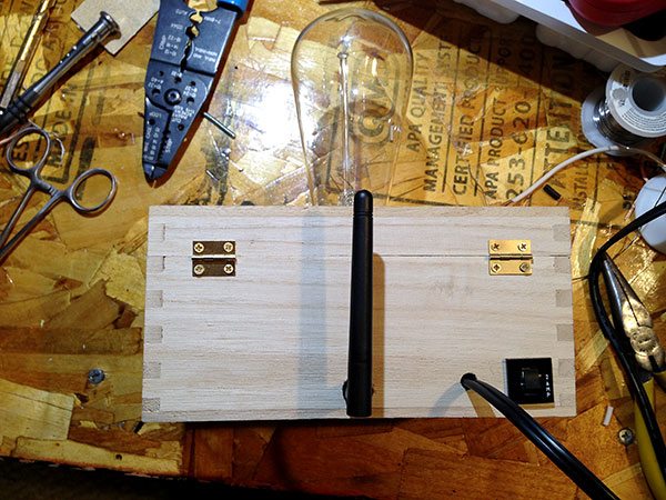
The house notification was arguably the funniest and most satisfying part of this whole thing. Being able to take an idea that you’ve had in your head for a long time and manifest it IRL is very satisfying.
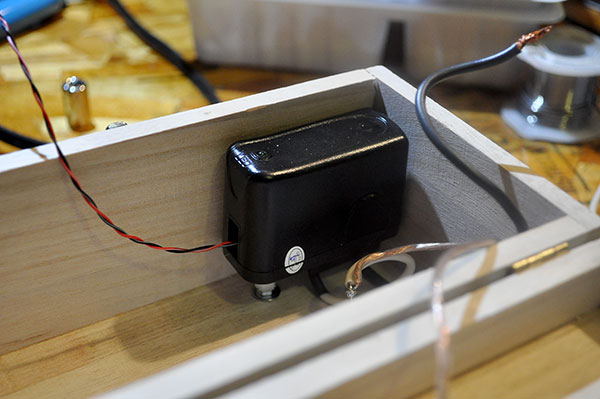
I used a cheap (paid ~$2 for it) wood box from Michaels (craft store) to house everything in. The box came unfinished, I beat it up a bit to give it some texture before I stained it.
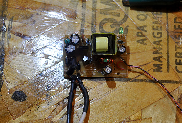
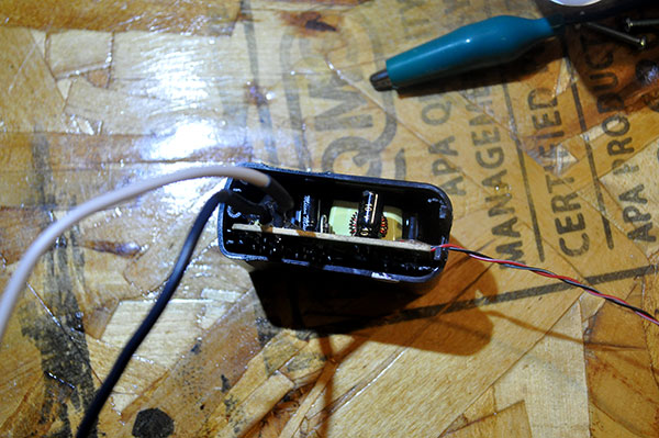
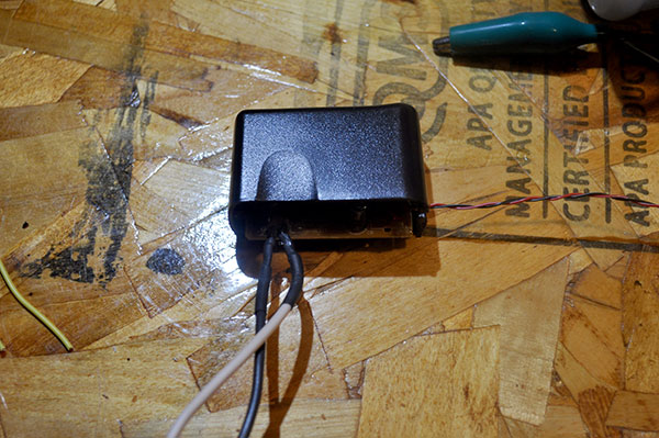
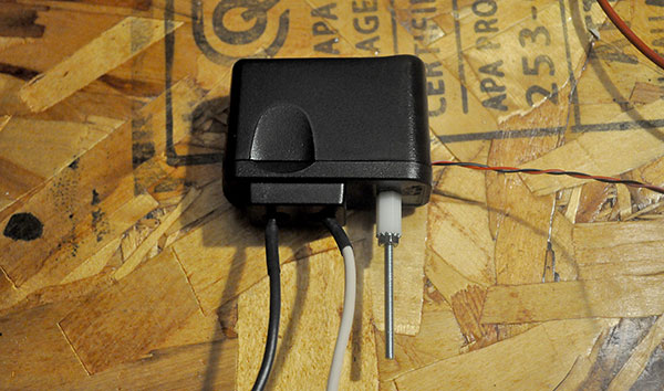
I needed 5v power for the Arduino and XBee, 120v for the bulb but I only wanted one power cable coming out of the box. I hacked a 5v wall-wart power supply so I could hardwire and mount it inside the box.
First Issue
I can’t begin to describe to you how utterly frustrating tracking down the following issue was. I’ve condensed the process down a lot, it took several weeks before I had it figured out. Looking back some of the things I tried, tests, etc. seem silly but they lead me to the cause… eventually.
At this point I’ve tested everything “in the lab” and done limited “field” testing to make sure the XBee signal would get to the house (I’d done preliminary testing before this so I was pretty sure it would work). So far everything has worked swimmingly. Now that I’m done putting everything together I’ll start more extensive testing.
I’ve moved the mailbox outside on the deck mostly to make sure there are no leaks. Coincidentally, we’ve been getting really low temps at night and I’m seeing an odd issue. The delivery door works fine but the retrieve door is not triggering the sequence as it should. I’m thinking it’s due to the cold but why is it only affecting the retrieve door?
I’ve determined that it’s the cold causing the issue. If I leave the mailbox outside long enough for it to get cold, and then bring it in and let it warm up slightly, everything works. Currently, the issue seems to be isolated to the retrieve door (i.e. the retrieve sequence does not run as it should when the retrieve door is opened).
Since the issue seems to be with the retrieve door, I’m wondering if it might be the reed switch. The switch’s datasheet indicates that it should continue to function well below the temps it’s being exposed to, but maybe it’s damaged or defective. The switch is supposed to be sealed so moisture should not be able to get inside it. I’m wondering though if it’s cracked and moisture is getting in and freezing the contacts.
I’ve done two tests on the retrieve door switch and found that it’s working correctly:
-
After leaving the mailbox outside and having the issue occur, I checked that the reed switch was engaging and disengaging when it’s supposed to.
-
I removed the retrieve door switch, put it in the freezer for an extended period of time and checked that it engages and disengages properly.
I put a bit of foam insulation around the retrieve reed switch. I’m grasping at straws at this point. Even though it tested fine, I still think the reed switch might be the cause since the only issue seems to be with the retrieve sequence not working when it’s cold.
By this point I’ve mounted the mailbox at it’s permanent location. Temperatures have risen and it’s working correctly. I had to wait till they dropped again to see if the insulation helped anything. Spoiler, it didn’t.
We are getting really cold temperatures now (sub-freezing) and I’m still seeing the retrieve issue as well as others. Now, the house indicator is not triggering properly. It will turn on but not off and vice versa. I’m also observing that the XBee wake timing seems to be off. I’m not sure the issues are related or I’m seeing two different issues with different causes.
I’ve checked all the datasheets I could find and they all indicate that the hardware should be more than ok at the temps they are being exposed to. I’ve adjusted the sketch so that the Arduino and XBee are awake longer before they do anything. I’ve also set it so the XBee sends the on/off characters multiple times. I’m wondering if putting them to sleep is allowing them to get too cold and letting them run for a bit before use will help.
Adjusting the timing has had no effect so I’m going to try insulating the enclosure. I’m wondering if the clock on the Arduino might be the culprit, maybe it’s getting too cold. It would make sense, the issues I’m seeing all seem to be timing related. I’ve also checked voltages and current draw, both seem ok.
At this point we were seeing temps in the teens. Not normal but not unheard of either.
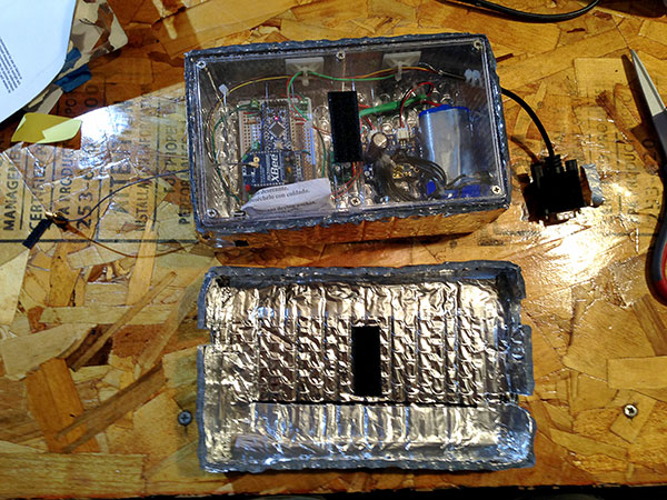
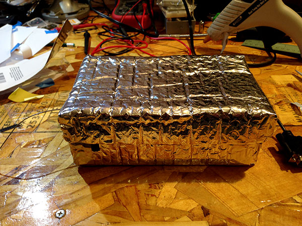
No changes with the insulation, I even tried insulating the mailbox itself. Now, I’m concerned that it might be moisture getting inside the case, settling on the components, freezing and expanding. That would explain why it works when it warms up. Even though I don’t see any signs of moisture on the components, I’ve moved everything into a an IP rated enclosure. I’ve also swapped out the Arduino.
The new enclosure didn’t solve the problem. I knew for a fact that it was the cold because I could bring the mailbox inside, let it sit for 5 minutes and it would work perfectly. At this point I’m thinking it may just not work, the only solution I can think of is to use a heater to keep everything warm but with the power limits that’s not an option.
I’ve decided to test to see if I can induce the issues. I’ve taken the enclosure out of the mailbox, sealed it in a zip-lock and put it in the freezer for 30 minutes.
Repeated freezer tests confirm that it is cold that causes the issue. 30 minutes in our kitchen freezer is enough to induce it. I’ve run the tests with the battery in place and left out. I’m checking voltages and current draw after 30 min stints in the freezer and finding all ok. I did notice that when cold, the MintyBoost is producing a high-pitched whine, not consistently but more often than not.
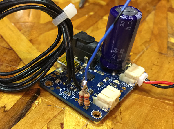
Found The Issue!
When cold the MintyBoost must be producing unstable power. It’s whining is what tipped me off. My multimeter is showing that the voltage is fine but I bet if I had it hooked to an oscilloscope I’d see it plain as day. I’ve added a capacitor inline with the MintyBoost output, which alleviated the cold whining and everything seems to be working correctly now, even when cold.
Second Issue
At this point I’ve put everything back together and put the mailbox back into service. It worked perfectly, even in the cold… for a few days. Then, the battery died. It occurred to me that I never topped-off the battery after all my freezer testing. So, I ran an extension cord out to the mailbox and charged the battery off mains overnight. It worked great for a few more days after that. Incidentally, those few days were sunny. When it started to rain again, I started to get a dead battery again.
The battery is dying much too quickly, within a few days if it’s not sunny out. I’ve brought the mailbox inside while the battery is dead to take measurements.
Measuring the current at the battery I’m seeing a draw of 150mA with the Arduino and XBee sleeping. The battery voltage is 2.5v, the lowest the battery’s internal circuitry will let it discharge (i.e. it’s dead). This tells me that the MintyBoost is likely the cause of the high current draw, it’s trying to boost the 2.5v and sucking a lot of power doing it.
I think I have a handle on what’s going on. The battery starts off fully charged. With successive sunny days, everything is fine, the draw on the battery is low enough during the night that it does not lose much charge. During the day the system is powered by the solar panel and the battery is able to charge.
However, to many successive days where the system is dependent on the battery and we start to see a drain on the battery. As the battery voltage drops the MintyBoost has to work harder (draw more current) to boost the voltage. At a point the battery voltage becomes too low to be usable but the MintyBoost still tries to boost it — causing a constant high draw on the battery. The battery is discharged enough at this point that the solar panel alone is not enough to charge it back up. Keep in mind that the panel can ideally produce only 330mA of current.
The only solution I see is to eliminate the MintyBoost and move to the 3.3v Pro Mini. For that to work I’ll need to:
-
Move the power input wire to the RAW PIN on the 3.3v Mini. This will pass power through the Arduino’s on-board voltage regulator. This is necessary because the battery’s charged voltage is +4v and the voltage will be as high as 6v when running on the solar panel.
-
Move the XBee power over to the Arduino’s VCC pin so that it’s feed a regulated 3.3v.
-
Change out the 150 Ohm indicator LED resistors with 50 Ohm, also change the dome-light resistor.
After making the necessary changes and swapping the 5v Mini with the 3.3v Mini, I took current measurements (note: these measurements were done at the battery.):
-
Arduino and XBee asleep: 0.58mA — 221 days of runtime.
-
Arduino and XBee Awake (sketch running/XBee transmitting): 65.9mA — same as before.
-
Arduino and XBee asleep w/notify LEDs on: 10.8mA — 11.8 days of runtime.
After swapping the Arduino and other components, I put the mailbox back in service and it’s been running well past its previous failure point for weeks. I’ll also note that every time I’ve checked it so far the charger has indicated the battery is fully charged.
Code
The Arduino code for the mailbox and house indicator is available on Github. It’s pretty simple and (I hope) easy to follow. The mailbox side is the most complicated because of having to put the Arduino to sleep and because it’s just doing more. I’ll give a brief overview of the mailbox code.
Mailbox Code
When powered on the Arduino goes into the main loop where it immediately puts the XBee to sleep, waits half a second, and then puts itself to sleep.
1
2
3
4
5
void loop() {
  digitalWrite(XBPower, HIGH);  // Put the XBee to sleep.
  delay(500);                   // Wait a half-second and then go to sleep.
  F_sleep();                    // Call the sleep function
}
Once the Arduino is asleep it stops processing the sketch and won’t do anything until an interrupt wakes it up. At this point the Arduino is “waiting” for the delivery door to open, if the retrieve door is opened it will wake up but then immediately go back to sleep.
When the mail is delivered the mail person will open the delivery door, this will trigger the interrupt and wake the Arduino. The Arduino will run a function and check which interrupt woke it up, see that it was the delivery switch and process accordingly:
-
Turn the notification LEDs on.
-
Wake the XBee and wait a second.
-
Send a “1” character out the serial line, wait 5.5 seconds and then send the “1” a second time. Wait 5.5 seconds.
-
Put the XBee to sleep, wait a half-second, put itself to sleep.
I have the “1” transmitted twice just to be sure that the house notification gets it. I wait 5.5 seconds between transmissions to make sure that the XBee is finished before transmitting again, or going back to sleep.
1
2
3
4
5
6
7
8
9
10
11
12
13
14
if (digitalRead(DeliverSW) == HIGH && delivery == false) {
  digitalWrite(NotifyLED1, HIGH);  // Turn the external notification LEDs on.
  digitalWrite(NotifyLED2, HIGH);  // Turn the external notification LEDs on.
  digitalWrite(XBPower, LOW);      // Turn the radio on.
  delay(XBeeWakeupDelay);          // Give the radio some time to settle after waking up.

  // For the sake of making sure the house notification gets its ON signal we send the ON command out, wait 5.5 seconds and then send it out again until transmitCount is equal to timesToTransmit.
  for (int t = 0; t != timesToTransmit; t++) {
    Serial.println("1");       // Send a character out the serial to turn on the house notification.
    delay(XBeeTransmitDelay);  // Give some time for the transmission to end before we send the next one.
  }

  delivery = true;  // Set this so we know the mail has been delivered and don't run the delivery sequence again before the retrieve door is opened.
}
At this point the Arduino and XBee are asleep again and waiting for the retrieve door to open, if the delivery door is opened it will wake up but then immediately go back to sleep.
When the retrieve door is opened the Arduino wakes up, turns the notification LEDs off, turns the dome LED on and then waits till the retrieve door is closed.
When the retrieve door is closed the dome LED is turned off and then the same process is followed as during delivery, except that a “0” is transmitted to tell the house indicator to turn off.
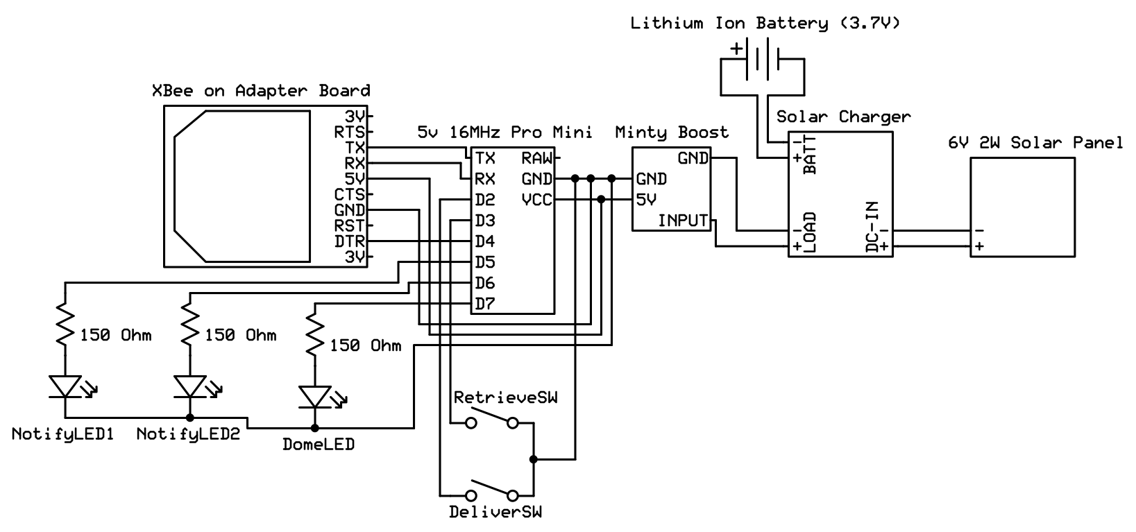
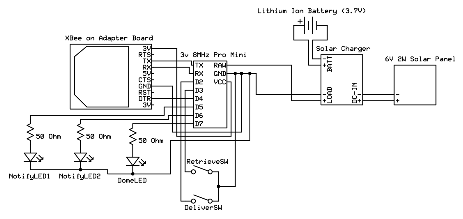
Schematics
Below are two schematics, one shows how the 5v version with the MintyBoost was hooked up. The other shows the 3v version without the MintyBoost (click to embiggen).
Postmortem
The power consumption between the 5v setup and the 3.3v setup is dramatic but not that surprising when you think about it.
-
The 3.3v Pro Mini runs at 8MHz vs. the 16MHz the 5v Pro Mini runs at.
-
In the original (5v) setup I was boosting 3.7v to 5v via the MintyBoost, then regulating it down to 3.3v for the XBee. That’s grossly inefficient. With the 3.3v setup I’m just regulating the input voltage going to the Arduino and XBee; much more efficient.
I should point out that the MintyBoost itself is not at fault. I was using it for a purpose that was outside the scope of its design. In any case, the issues with its operation in cold temps were easily solved by adding a capacitor. Beyond that the issue with it causing high drain was more an issue with my implementation. The MintyBoost has it’s use(s), this just isn’t one of them. When running on a charged battery the MintyBoost is very efficient (if I recall it’s above 85%) and does not cause excessive draw on the battery.
The first part of this project was easy and went smoothly, I was caught off guard when I started to have problems. I’ll admit that this one put me through the ringer. At one point I told the Wife-Unit® that the only way to get it to work would be to run power out to the mailbox. Frankly, there were a couple of times I was ready to give up on it.
In hindsight I can see that the root of the problem was my unwillingness to go with the 3.3v Pro Mini from the start. I knew it was an option but I ignored it. It’s silly, especially when I knew (in this case) there was no practical difference between the two but I wanted to stick with what I knew and had used before.
I hate making mistakes and would rather things just work right off the bat. But the fact of the matter is that I learn a heck of a lot more when things don’t go as expected and I’m better prepared for the next project and its problems.
Possible Add-ons/Improvements
-
Add a indicator/display in the house that tells you the status/voltage of the mailbox battery when mail is delivered and retrieved.
-
Add a temp sensor to the mailbox so you can record the temp when mail was delivered and retrieved.
Update 1
On the house side I added a DS1307 RTC (Real Time Clock) so I can record the date and time mail is delivered and retrieved.
For giggles, because I was curious, I added a DS18B20 temperature sensor inside the mailbox. I wanted to know the temperature inside the mailbox/enclosure so the sensor is inside the enclosure that everything else is in. It’s not meant to measure the outdoor temperature.
I also added a voltage divider to measure the battery voltage.
To display the information I added an LCD display to the house side.

DS18B20 temp sensor was added to measure the temp inside the mailbox/enclosure.
Voltage divider added to the aux battery output on the solar charger to step down the voltage so it can be measured by the Arduino.
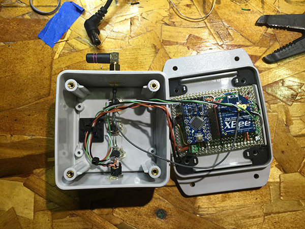
Update 2
Because of the distance (~120′) to the house, having chain-link fence in front of it, and a house, the signal from the Mailbox XBee to the house was always weak. The weak signal was basically completely dealt with by programing the mailbox to send the data more than once (4x). There were times (every blue moon) that I noticed the house indicator did not trigger but 99.9% of the time it worked properly. However, after we replaced the Windows in our house, the only way to get the house indicator to trigger was to place it in front of, or very close to the front window (in line of site of the mailbox).
My guess is that our new windows use a metallic coating (to block UV) that attenuates the signal enough to effectively block it. To combat this I made a repeater that’s mounted outside above the window (mostly out of sight). The repeater simply receives the data from the mailbox and spits it back out. I used an Arduino along with the XBee and added a DS18B20 temperature sensor that sends the temp of the repeater along with the mailbox notification and data.
Update 3
While adding the code for to measure the battery voltage and temp at the mailbox, I did a couple of power optimizations in the code as well. I set unused PINs as outputs, turned off the ADC while sleeping, and turned off brown-out detection. These optimizations made small (very?) improvements in power consumption in the various modes. Since I’ve added the ability to measure the battery voltage, I’ve not seen it dip below 4v (even in non-sunny months).