Automatic Server Room Exhaust
The Problem
I have a home “server room” that houses a couple of servers and other network hardware. In fact this site is being served to you from a VM running on a server sitting in that room.
If you’ve spent any time around servers (or any electronics for that matter) you know that they generate heat. I’ve recently consolidated a couple of physical servers by virtualizing them but the remaining physical servers, switch, cable modem, and UPS still generate about 2000 BTUs of heat. That’s about the same heat output as a small space heater.
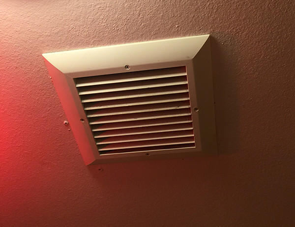
The “server room” is a repurposed 30sq foot bathroom that is off of a main room (think of the typical master bedroom/bathroom setup). Managing the heat produced by the equipment has been an issue mostly solved by keeping the server room door open (to keep heat from building up) and running the existing bathroom exhaust fan.
My main issue with the current setup is having to keep the server room door open. This is especially an issue in the summer because the heat produced from the equipment is enough to overwhelm any cool air being pushed into the main room from the central AC. This makes both the server room and the main room perpetually hot. Also annoying is the noise from the equipment, and having to keep the door open prevents me from being able to doing anything to reduce dust incursion into the server room.
The Idea
Obviously I need to replace the existing exhaust fan with a more powerful one. I don’t want to run AC in the room and I don’t think I need to. I’m willing to let the room get as hot as 80°, maybe even hotter. the equipment is more than capable of handling high temperatures.
My initial plan is to replace the existing exhaust fan with a much more powerful one. I’ll add a vent in the server room door so cool air will be pulled in from the main room. Being able to keep the door closed will isolate the server room, preventing its heat from spilling into the main room. It will also help reduce dust incursion into the server room by allowing me to add a filter to the vent in the door.
This, I think, will work even during winter when the furnace is in use. Since the air in the main room will still be cooler than the air that builds up in the server room. Keep in mind that the idea is prevent the buildup of heat by exchanging the hotter air in the server room with cooler air from the main room.
Where To Exhaust
I don’t want to just vent the air into the attic. Venting warm air into a cold attic during the winter can cause condensation and moisture buildup. Unfortunately, this wasn’t something that the previous owners took into account and the existing fan simply vents into the attic. Even if there was proper ducting, most bathroom type fans use ducting that is too small for the amount of air that I need to move. So, I’ll need to add ducting to an outside vent. Since I don’t want to mess around with cutting a hole in the roof, I’ll put the vent on the side of the house. This is also ideal since the fan and side of the house will be in close proximity.
Now, I could stop here and just vent the host air outside all the time but two things bother me:
-
I don’t necessarily want the exhaust fan on all the time. Just when the temperature in the server room goes past a threshold.
-
It does not make sense to vent the warm server room air outside all the time. During winter (i.e. when we’re trying to keep the house warm) it would be nice to vent the warm air into the parts of the house that we’re trying to keep warm. I’m generating (and paying) for the heat, might as well use it. While it’s not a lot, it’s not nothing.
So, I need a new exhaust fan that connects to to a thermostat of some kind. I also need a way to vent the air either outside or inside and I want it to all be automated.
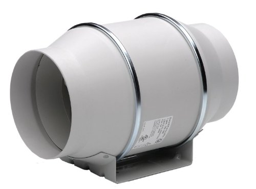
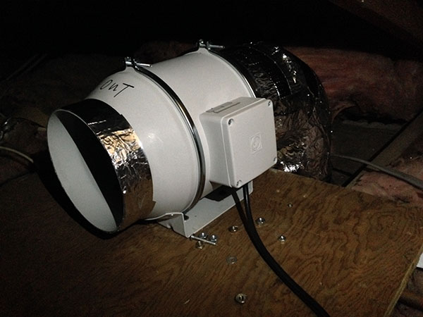
The Fan
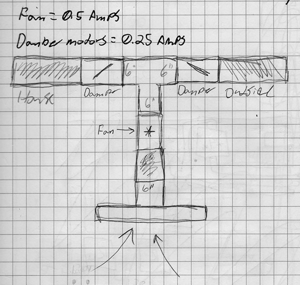
Most of your household exhaust fans are a joke. I need a fan that actually moves air, not a typical one that just makes noise. After some digging I came across Soler and Palau’s TD-MIXVENT exhaust fans. There are not a lot of exhaust fan reviews, but everything I read on S&P fans was positive. After some thought I decided on the TD-150, which is rated to 293 CFM @ 0 static pressure.
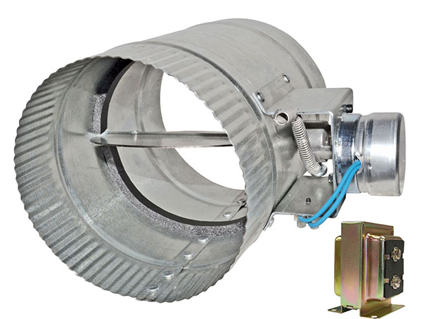
Dampers
I need to be able to control if the server room air is vented outside or inside. I had given up on automating this because motorized dampers are stupid expensive. However, after a lot of searching and some luck I came across 6″ motorized dampers that are reasonably priced. I’ll be using the normally closed version of the damper, when the damper motor is not powered the damper will stay closed.
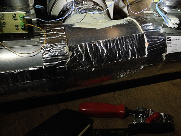
Ducting
The TD-150 fan is made to connect to 6″ ducting and the dampers are also 6″. I don’t want to reduce that size at all so I’ll use 6″ insulated flexible duct. The insulated part is important because: a) warm air will be going through the ducting, if it’s not insulated condensation can form when the attic is cold in the winter and b) I don’t want the warm server room air to lose any heat when venting into the house.
Control
Ok, so I have an exhaust fan, motorized dampers, and what will become an obvious abundance of time on my hands. I want the fan to turn on and off automatically based on the temperature in the server room. This is for two reasons: 1) There will be times (morning, night, winter) when the room will stay at a reasonable temperature on it’s own, there is no need to run the fan during these times 2) It would make no sense to exhaust the air from the server room into the house if it’s not at least as warm as the temperature that we keep the house at during the winter. I also want the dampers to open and close automatically based on where the air should be vented.
I’d originally thought of just using a switch to manually control the dampers and an off the shelf thermostat for the fan. It then occurred to me that I could tie the two functions together and make a system that was truly automated.
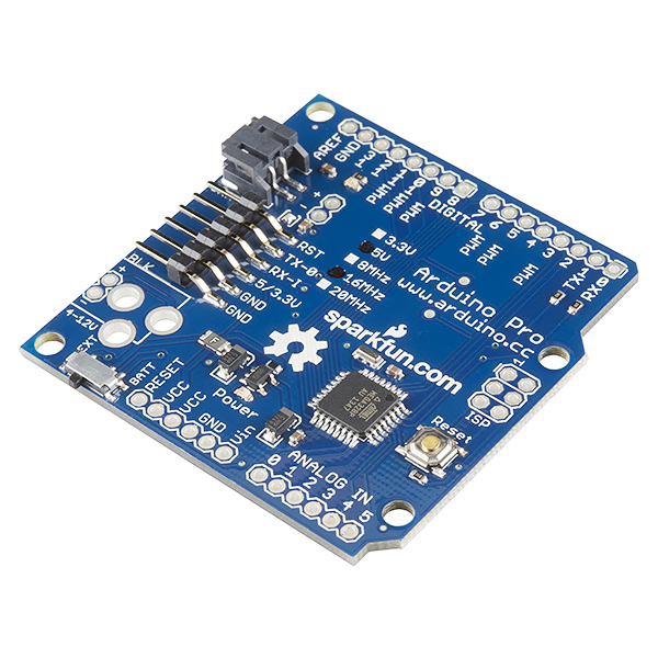
So, I’ll be use an Arduino to interface with and control all the hardware — temperature sensor, fan, and dampers. I happen to have a few Arduinos on hand that I got cheap via Sparkfun’s Arduino birthday sale. I’ll use an Arduino Pro 5v.
Controlling The Fan
I have a DHT22 humidity and temperature sensor that I’ve been playing with, intending to use it for another project. While I don’t need humidity readings, I already have it on hand. I’ll use it to measure the temperature in the server room so the fan can be turned on or off appropriately.
The TD-150 runs on mains voltage, it consumes about 0.5 amps. The Arduino obviously can’t control it directly, so I’ll use a solid state relay (SSR) to interface it with the Arduino. Since I’m paranoid and believe it’s better to over engineer, I’ll use an SSR rated for 8 amps. This particular SSR also has a built in snubber circuit, which is nice since it will be switching an inductive (motor) load.
Controlling The Dampers
The dampers are powered off 24 volts AC via an external power supply. The dampers are normally closed, so they are only open when the motors are powered. I’m using two dampers but only one will be on at a time (both may be on at once but only briefly) so I’ll just use one power supply for both dampers. I’ll use the same model SSR that I’m using for the fan to turn the dampers on and off. The dampers draw 0.25 amps so the S102S11F can more than handle the load of the dampers, and again the built in snubber circuit is handy.
Damper Automation
The following information may be specific to my furnace. Not all furnaces use the standard wiring. When it doubt proceed with caution, measure, and test.
There will be two possible paths for the vented air to take. Either outside or inside. But how do I automate that choice?
It stands to reason that when the furnace is on we are trying to warm our house and when it is off, it stands to reason that we are not trying to warm the house. The furnace already automatically heats or cool our house via its thermostat. Hum… it turns out that the thermostat has separate signal wires for the heater, AC, and fan. Each of those signal wires connects to a respective relay on the furnace/AC unit to control the specific function.
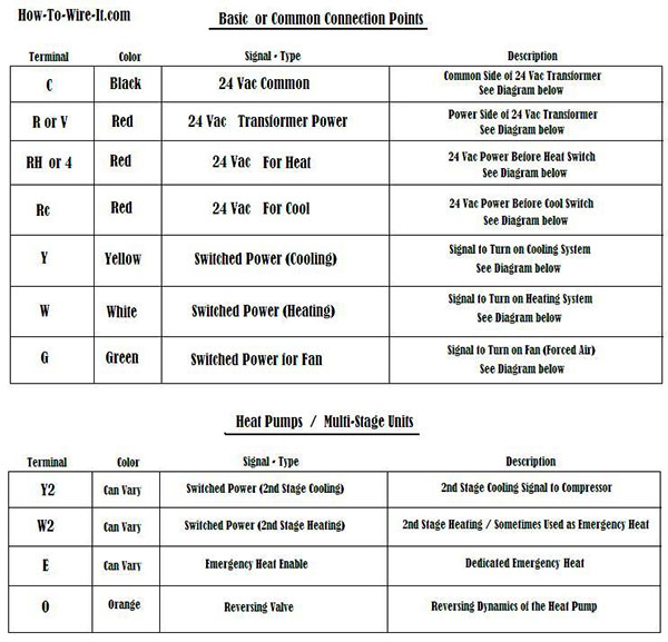
When the thermostat calls for heat, it sends 24v AC between the W wire and Common, which powers a relay in the furnace, turning the heater on. When it wants to turn the heater off, it turns off the 24v. Fancy that.
I can use that 24v to detect when the heater is on or off and have the server room air directed appropriately. However, 24v AC is most definitely not Arduino friendly. AC input DC output capable SSR relays that run on 24v seem to be hard to find. I can use a mechanical relay but I prefer to use solid-state components if possible.
I could rectify the 24v AC signal and use a voltage divider to knock the 24v down to a Arduino freindly 5v signal but I’d have to do full-wave rectification (otherwise the signal will oscillate, causing potential issues) and it just feels messy.
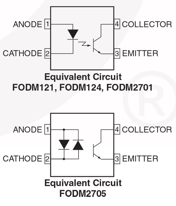
After some digging I found that there are AC capable optoisolators. I’ve used optoisolators before in my Coin Operated XBOX but assumed that they only worked with DC because they use an LED. While it’s possible to power an LED with AC (I’ve seen cheap LED Christmas lights that run on straight AC) the LED will oscillate (turn on/off) based on the input frequency, which is 60Hz here in the US. This on/off oscillation of the LED is not necessarily perceptible to the naked eye but makes it unusable as a microcontroller input because the microcontroller would see the input constantly flapping one way or the other.
An AC capable optoisolator, however, uses two LEDs connected in inverse parallel — the LEDs are connected in parallel but their polarities are reversed — in order to compensate for the oscillation of AC. Since the polarities of the LEDs are reversed, as the AC oscillates only one LED is on at a time but because an LED is always on, a stable signal is created.
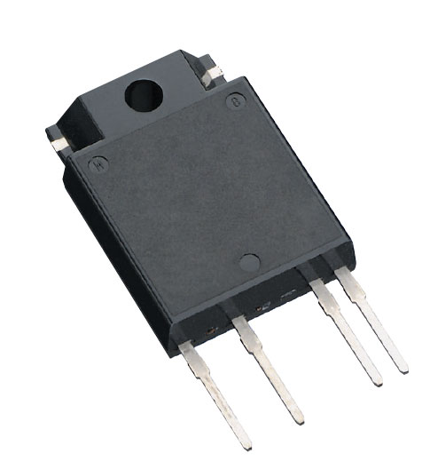
Further digging produced an even better option, a device designed specifically for this type of application, the MID400.
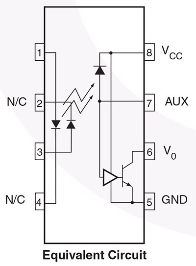
The MID400 is a “AC Line Monitor Logic-Out Device.” It’s specifically designed to act as an interface between high voltage AC and a low voltage logic device. Like an AC optoisolator, it uses two LEDs connected in inverse-parallel to compensate for the AC oscillation. The datasheet isn’t entirely forthcoming on what’s going on beyond that other than to say that “a high gain detector circuit senses the LED current and drives the output gate to a logic low condition.” It’s probably a photodetector connected to a transistor. Anyway, it’s one heck of a little IC — it can isolate up to 2500 VRMS as long as you stay within the input current limit. In any case, it can more than handle my application. The input requires a minimum of 4mA (25mA max — remember it’s powering LEDs) to trigger the logic output. This low current requirement is key, since I’ve read that furnaces can be finicky if high loads are connected to the signal lines.
The upsot of all this is I can use the MID400, a device specifically designed for this type of thing, to detect when the furnace is heating the house. When the furnace is heating the house the input of the MID400 will see 24v and drive the output side LOW. And when the furnace is off, the output will be HIGH. I simply program the Arduino to open and close the dampers according the state of the MID400 output: LOW (furnace on) = vent inside, HIGH (furnace off) = vent outside.
One thing that’s important is the input resistor for the MID400. There are a few things to keep in mind: 1) You need to choose an input resistor value that limits the input current to within the limits of the device (25mA max). 2) The MID400 needs a minimum of 4mA to trigger. 3) Based on the input voltage and current you need to use an appropriate wattage resistor.
Based on the MID400 datasheet the formula to calculate the input resistor is:
1
InputResistor = (InputVoltage – LED-FowardVoltage) / MinLEDCurrent
The datasheet specifies that the forward voltage of the LEDs in the MID400 is 1.5v. The MID400 needs a minimum of 4mA to trigger the output, I want to draw as little as possible (to avoid issues with the furnace) but still error on the side of caution, so I’ll calculate for 5mA (note that for the calculation you need to convert mA to Amps):
1
2
3
4
5
InputResistor = (24v – 1.5v) / 0.005mA

Then:

InputResistor = 22.5v / 0.005mA
Finally:
1
Input resistor = 4.7k (the exact value is 4.5k but that’s not a standard resistor value).
The next question is how much current will the input resistor need to dissipate. To calculate that I use Ohms Law:
1
24v x 0.005 Amps = 0.12 watts
The input resistor will be dissipating 0.12 watts, so a run-of-the-mill 1/4 watt resistor will work just fine.
The Build
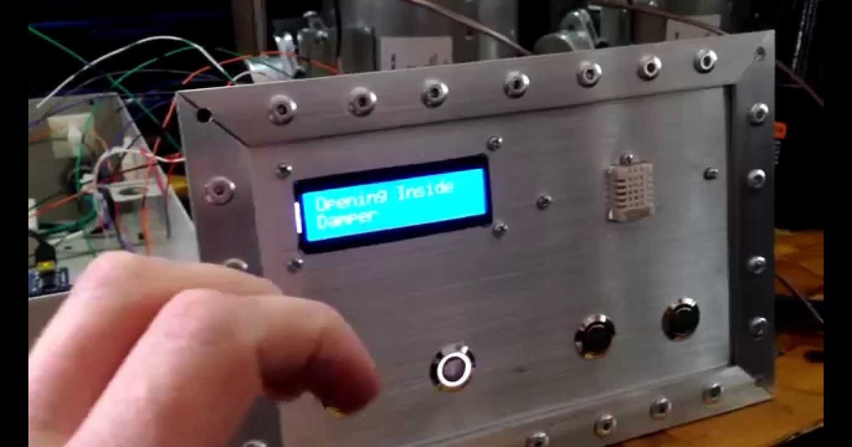
Control Box
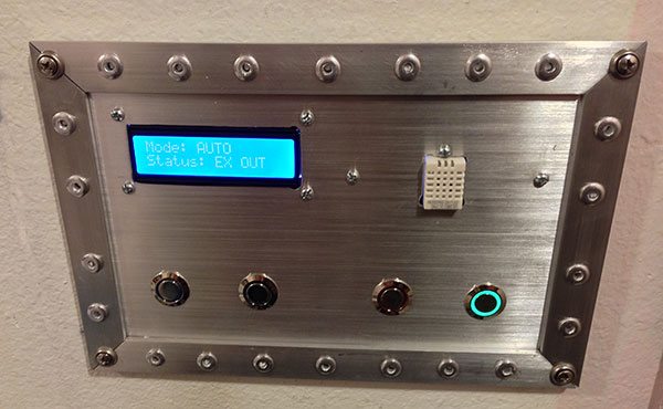
I’ve worked out how to automate everything, I figure I’ll add a LCD display to show the temperature (and humidity ’cause it’s there) and status of the system. Also manual controls would also be nice, so I’ll need some sort of control panel.
To reduce the number of wires that I have to run, particularly ones carrying mains voltage, I’ll plan on putting the control hardware (Arduino, relays, etc.) in the attic near the fan and dampers. I’ll run cable from there to the control panel in the server room.
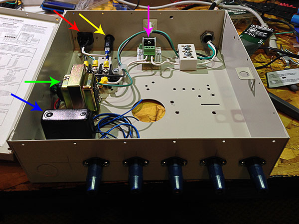
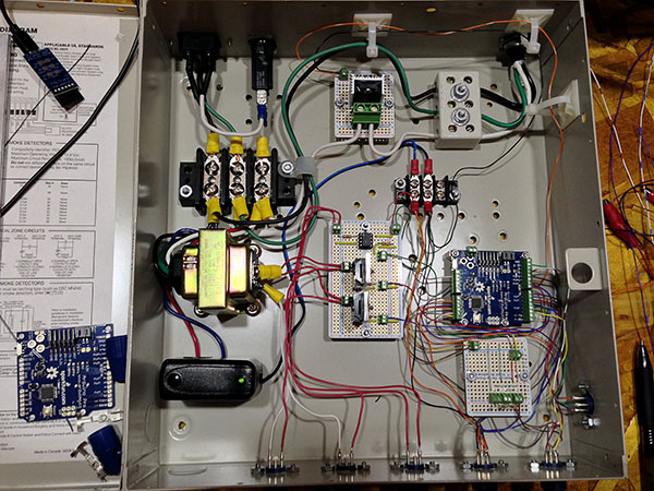
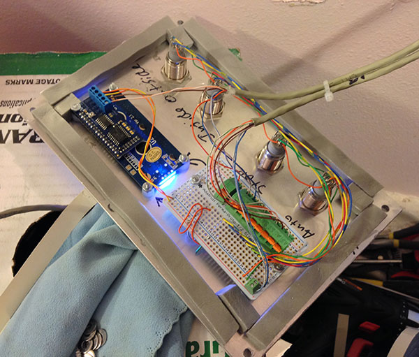
I have an old metal alarm box that I’ll use to house all the control hardware.
-
Red: 120v input.
-
Yellow: 2amp breaker (just in case).
-
Pink: Fan SSR (heat sink is really unnecessary but I had it). Output to the fan goes to a plug going out the upper right corner of the box.
-
Green: 24v transformer for dampers.
-
Blue: 5v power supply for the Arduino.
I included the 2 amp breaker as a precaution, cheap insurance. The mains input goes to a terminal block where it’s distributed to the damper transformer, the 5v Arduino power supply, and the fan SSR.
Even though I’m using two dampers, only one will be on at a time. Actually, when the dampers switch they will both be on at the same time but only briefly. In any case one transformer can handle both dampers being on so I’ll only use one 24v transformer for both dampers to save space and wiring.
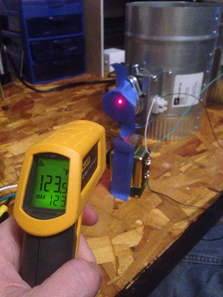
One thing to note, the dampers are opened via a motor which, in the case of the normally closed dampers, is continuously powered when the damper is opened. When powered, the motor gets hot. This is, as noted by a Suncourt rep. that I asked, “normal.” Just make sure there is plenty of clearance around the motors.
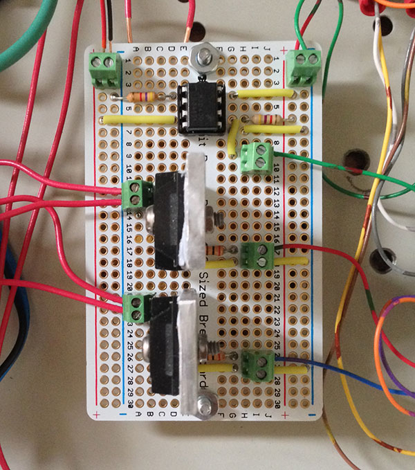
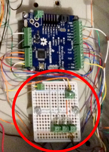
Since the damper relays and the MID400 both run off 24v, I put them on the same board. Note that the relays required a 200-Ohm input resistor and the MID400 has a 4.7k pullup resistor on the output side.
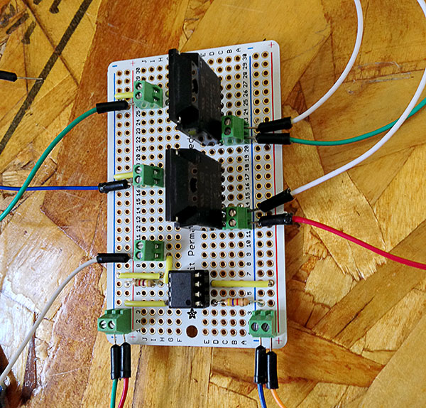
I later added pseudo heat sinks to the damer SSRs, which were not necessary in the least (they only have to sink 0.25 amps) but I was bored that day I guess.
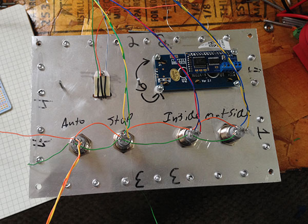
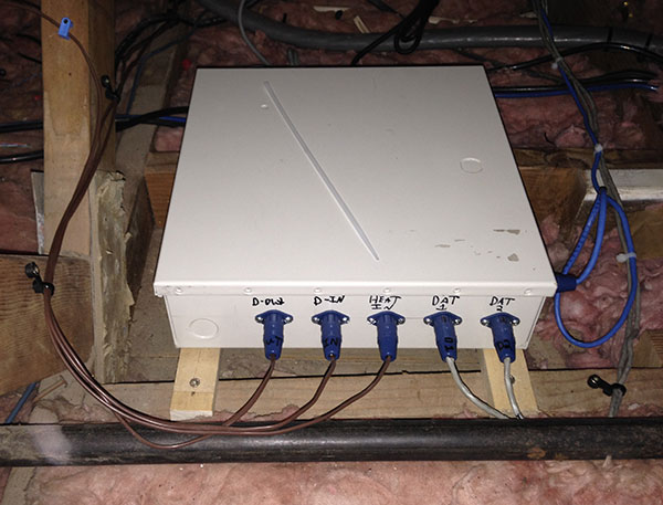
I’m using 3-pin XLR style connectors for the damper power output and the furnace signal input. 7-pin connectors are being used to connect the control panel that will be located in the server room. The control panel will have the temperature sensor, LCD display, and manual override buttons on it.
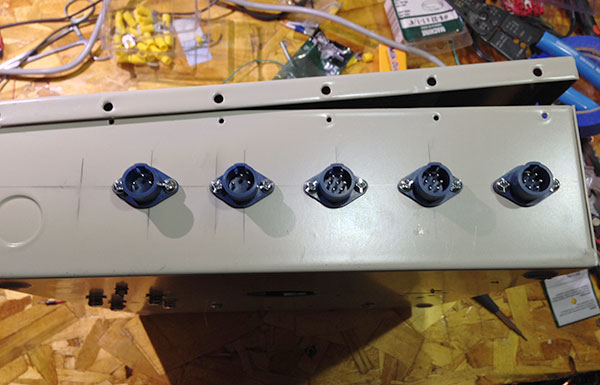
Note, this was a test fit and the third connector from the left is incorrectly a 7 pin connector. In practice it’s a 3 pin connector for the furnace input.
The control box turned out well. Everything fit in it at least. Note the board in the lower-right and the additional connector on the lower-right. I’ll explain these later.
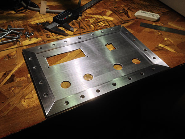
Control Panel
I wasn’t entirely sure at first how to do the control panel. It needed to have the display, temp. sensor, and manual buttons.
After much meandering I came up with an idea.
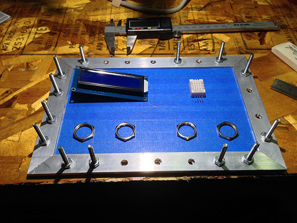
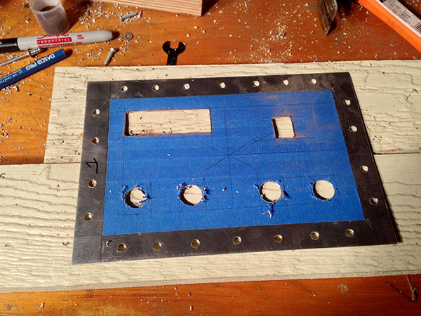
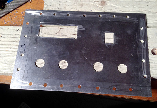
I didn’t want to leave the face of the panel looking so rough. Using 220 grit sandpaper and only sanding in one direction I gave the panel a “brushed” look. I used a jig to make sure the sanding block stayed parallel to the panel when sanding.
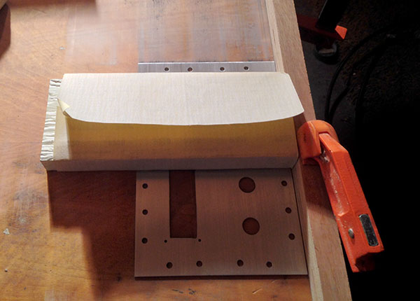
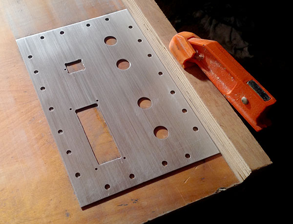
After several passes with the sandpaper, and making sure I went in the same direction as I did with the sandpaper, I used a scotch scrub pad to smooth and shine the panel.
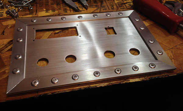
The border pieces and rivets were added mostly for looks but they do help to stiffen the panel as well.
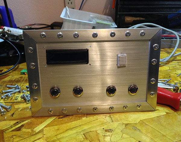
Next step was to mount and wire everything into the panel.
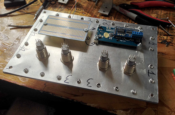
For ease of connection the buttons, temp. sensor and power are run to the green spring loaded terminal blocks. The LCD has it’s own terminal block for the data connections from the Arduino.
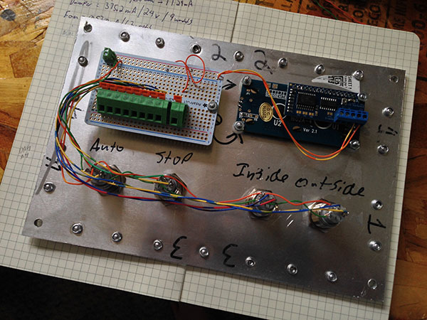
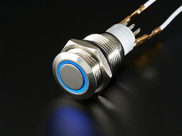
To be clear, I didn’t need to use 4 individual buttons for the manual controls. The only reason I did was because it made the Arduino programming a bit easier and it gave me an excuse to use the sexy lighted buttons. Each of the buttons is lighted by an LED and has the current limiting resistor built in.
A Note On The LCD
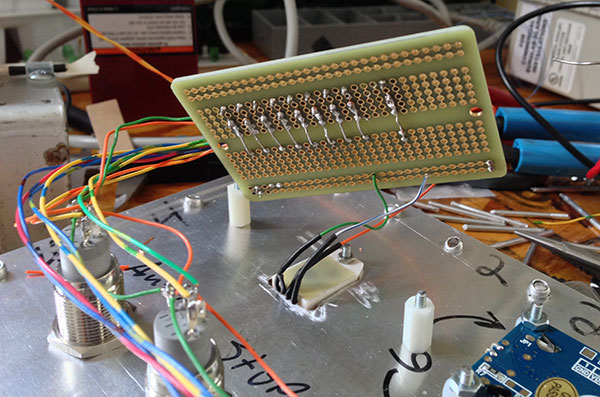
On it’s own the LCD needs 8 separate connections (6 data, 2 for power) to the Arduino to work. To minimize the number of wires I needed to run from the attic to the control panel I opted to use an i2c backpack which reduced the number of connections the LCD needed to 4 (2 for data, 2 for power).
The problem I ran into is that i2c does not like long cable runs. Initial tests with a long cable failed, the LCD would display garbage. After some digging I found that even with a short cable pull-up resistors on the SDA and SCL lines are recommended. With a long cable run they are a must.
4.7k seemed to be the value that was suggested to start with. Once I added the pull-up resistors to the SDA and SCL lines the display worked even with a ridiculously long cable. To error on the side of caution I added a separate board in the control box that had terminal blocks with the pull-up resistors in them. The SDA and SCL lines run from the Arduino to the “pull-up board” and from there to the control panel. Since the resistors were in the terminal blocks they would be easy to swap out if needed.
The run from the control box to the control panel ended up being ~6′ and the 4.7k pullup resistors proved adequate. I used 2 CAT5 cables between the control box and control panel.
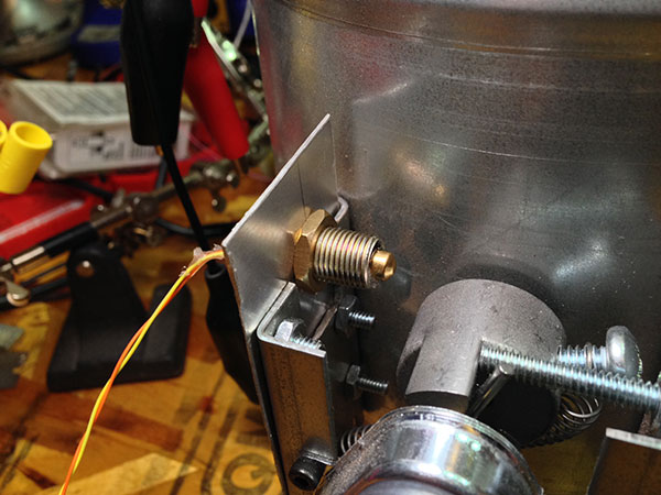
Damper State Detection
The rather long video below explains a modification I made to the dampers so the Arduino can know when they are actually opened and closed. The reed switch I used can be found here.
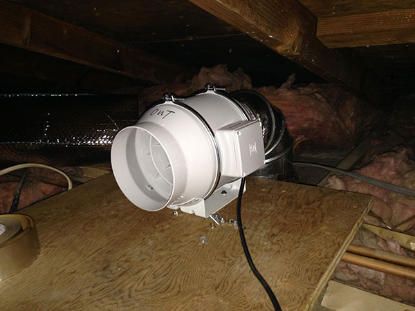
The Attic
Setting up the fan and ductwork was the most difficult part of this whole project. I hate attics.
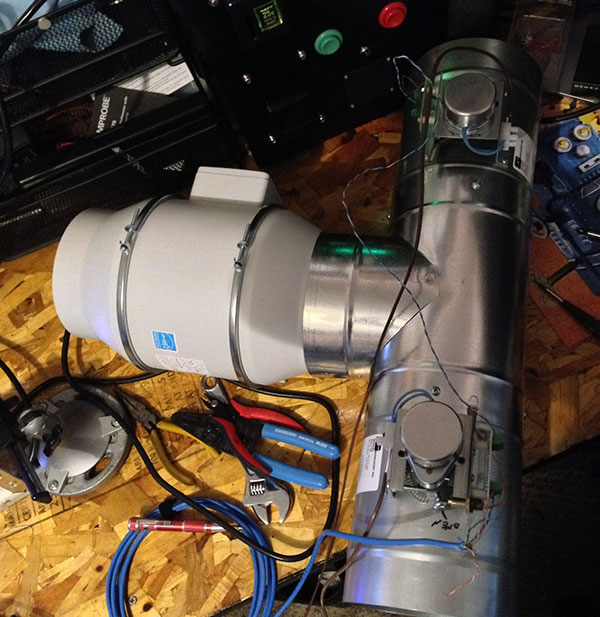
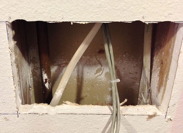
I used a piece of plywood as a platform for the fan and dampers. Fortunately power was already there from the old fan.
All the ductwork was insulated as much as possible.
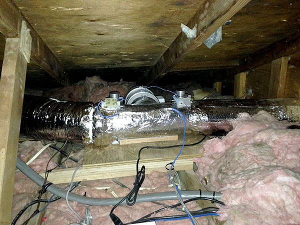
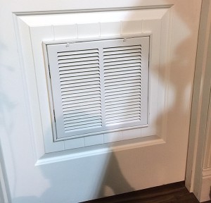
I put a filtered vent in the door to help pull the cooler room air into the server room.
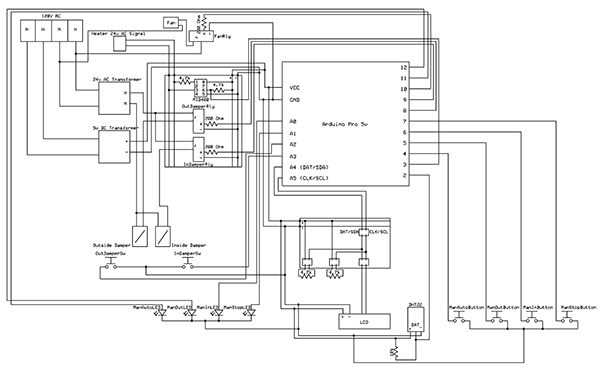
Schematic of how everything in the system is connected. Click here for the full size (pdf).
Programing
There is nothing particularly special about the Arduino program. It’s a simple state machine, that monitors the temperature of the server room via the DHT22. If the temperature goes above 75° and the furnace is on, it opens the inside damper and turns the fan on. If the furnace isn’t on it will open the outside damper to vent outside.
If the system is venting outside and the furnace comes on, the system will switch to venting inside. It will first open the inside vent, and then close the outside vent to keep from blowing air into a sealed system.
LCDs are a nice to have but are a pain to program for. I avoided using lcd.clear(); because it can cause flickering unless you jump through hoops to prevent it. Instead, I always made sure that whenever I printed to the LCD I filled all possible character locations.
1
2
3
4
lcd.print(“Mode: AUTO “);
lcd.print(“Status: ALL OFF “);
lcd.print(“Mode: AUTO “);
lcd.print(“Status: EX OUT “);
Notice the extra spaces at the end. They are added to clear out any characters that may have been previously printed in those positions. Since there are 16 positions, I make sure to add enough spaces at the end of each string so it fills up all 16 positions. Doing this avoids having to use lcd.clear(); and is actually updates the display faster than using lcd.clear(); does.
Getting the LCD to cycle through the various status messages took some thought to. The method I ended up using feels a bit messy but it works well enough.
Note also that no blocking delays are used. It’s especially important to avoid using blocking delays when you have a display or status indicator that needs to be updated in real time.
The Arduino sketch is available on GitHub.
Postmortem
In the weeks since the exhaust system was installed it’s been working wonderfully. The temperature of the server room has not risen above 80°. The system automatically turns the exhaust fan on and off according to the temperature in the server room. It’s been too warm to need the furnace, so all the venting has been outside, but testing has shown the that the system properly detects when the furnace is on and switches the dampers accordingly.
The only issue I ran into was the fan was being turned on/off too quickly for my taste. I had anticipated this and programmed in a delay option. I started with the delay set to 0 (no delay) but ended up changing it to 5 minutes. With the delay in place the system only checks the temperature of the room every 5 minutes so the system does not cycle on/off too quickly. Because of the way I wrote the program, a side effect of using the delay is that the temperature shown on the LCD can be as much as 5 minutes old. At the moment, I don’t consider this a problem but it may annoy me enough one day to fix.